Wavefront Propagation
Sound Source Behavior: Near Field, Transition, and Far Field
Understanding how sound waves behave near their source is crucial in various audio applications.
Here, we’ll explore the characteristics of sound in three key regions, including how sound pressure level (SPL) changes with distance.
Near Field & Fresnel Zone
Near field and Fresnel Zone is not exactly the same concept:
-
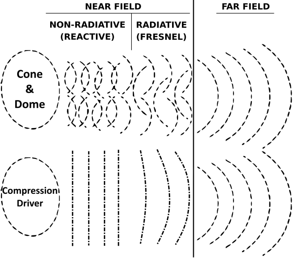
Fresnel Zone: This zone focuses on wavefront curvature. It defines an area where the curvature of the wavefront is important for accurate calculations of sound propagation.
-
Near Field: This zone focuses on sound pressure variations. It’s the region where sound waves haven’t fully developed their characteristic shape.
The near field, is the region close to the sound source where sound waves are flat or haven’t fully formed (chaotic), depending on source drivers and frequency.
In a single source they both end at the same place, at the transition distance, but not in the case of a composed source (Line Array, SBA).
Sources:
- “Sound System Engineering” by Carolyn Audio Engineering
- “Audio Engineering Handbook” by Gary Davis and Ralph Jones
The behavior of different sound sources in the near field can vary
-
Cone and Dome Drivers: Due to their operating principle and emissive shape, cone and dome driver wavefronts in the near field are complex and exhibit pressure variations. This complexity arises because the sound wave hasn’t propagated enough to establish a stable wavefront structure and diffractions occurs whith surround. As a result, the sound pressure can vary significantly depending on the frequency of the sound wave.
-
Compression Drivers: Compression drivers exhibit a more plane wave-like behavior in the near field, especially at lower frequencies. However, it’s important to note that this “flatness” is relative and depends on the specific distance and frequency. Even in the near field, the wavefront can exhibit some curvature or phase variations, especially at the edges. As the sound wave propagates through the horn throat, it starts to interact with the horn’s geometry, further influencing the wavefront shape.
-
Line Arrays (composed source): Line arrays, with their elongated design, can present a relatively flat wavefront becoming cylindrical-like with the distance in the Fresnel Zone, they can operate in the Fresnel zone over a very long distance in relation to and depending on their large size if the wavefront doesn’t encounter obstacles and the line array posisioned far from any obstacle or surface.
Special cases
-
Phase Plug on cone or dome drivers: They have a compression driver behavior, Phase Plug act like a compression of phase device and address the chaotic behavior of cone and dome in near field as we do with ReShape Phase Plug in tweeter waveguide by wavefront reconstruction.
-
Phase Shield on cone or dome drivers: At the reverse Phase Shield act as a diffraction tool to exibit even more the chaotic behavior of dome and cone drivers in near field. It use diffraction (accidents) as a directivity construction in high frequencies.
SPL Decrease in the Fresnel Zone
It can vary depending on the specific shape and frequency so no precise rules can be given, however, line arrays, due to their cylindrical-like wave propagation in Near Field, may exhibit a decrease in sound pressure level closer to 3 dB per doubling of distance compared to the 6 dB rule of the far field.
Transition Distance
The transition distance marks the point where Fresnel zone with their spherical wave transform into the far field’s characteristic flat wavefronts. This distance depends on several factors, including:
-
Source Size: Larger sources generally have a larger near field compared to smaller sources at the same frequency.
-
Sound Frequency: Lower frequencies tend to have a larger near field compared to higher frequencies for a given source size.
It’s important to note that in case of single source, the near field end when Fresnel zone basically end, but not for combined source like SBA or Line Array where Fresnel zone ends way further.
For a cone, dome and compression drivers :
In Line Array case :
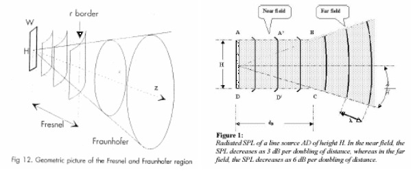
Formula can be found in Appendix.
Far Field (Fraunhofer Zone)
The far field, also known as the Fraunhofer zone, is the region where sound waves are considered to have minimal curvature. This characteristic allows for straightforward calculations and predictions of sound propagation through a space.
Behavior of Different Sound Sources in the Far Field
While the wavefronts in the far field are more predictable for all sources compared to the near field, there are still some subtle differences in how different sound sources radiate sound:
-
Cone and Dome Drivers: In the far field, cone and dome driver sound pressure follows the inverse square law for the most part. However, for large drivers, at the edges of the radiating area, there might be a slight roll-off in high frequencies due to diffraction effects. The interaction of the driver’s wavefront with the enclosure edges can also contribute to bending it towards a more rounded shape, further influencing the far-field behavior.
-
Compression Drivers with Horns: Once the sound wave exits the horn in the far field, it generally follows the inverse square law. However, the horn’s directivity pattern (how it focuses sound in specific directions) determines how the sound pressure is distributed in the far field, the midrange narrowing if present and horn mouth will also impact wavefront edge.
-
Line arrays: Line arrays, due to their design, tend to maintain a more coherent wavefront over a larger area in the far field compared to point source speakers like cone and dome drivers. This translates to a more consistent decrease in sound pressure with distance according to the inverse square law within the coverage area of the line array.
SPL Decrease in the Far Field
In the far field, sound pressure level (SPL) generally decreases by approximately 6 dB for each doubling of the distance from the source. This phenomenon is known as the inverse square law. It allows for simpler predictions of sound level at different distances in the far field. This decrease occurs because the wave propagation is spherical, and the expanding wavefront covers a much larger surface area with increasing distance.
Walls effect
In Far field and in a room , the shape of a wavefront typically changes, transforming into a plane-wave like behavior due to three factors.
Firstly, like a wave in a tube, the wavefront in a room can’t expanding infinitely on its sides, walls act as barriers, forcing the spherical wave to interact with them.
Secondly, wavefronts tend to travel perpendicular to the surfaces they encounter.
Thirdly, the further the wavelength propagate in the room, the more the circle section looks flatter in the room point of view.
This interaction with the walls essentially reshapes the wavefront, transforming its curvature into a more planar form as it propagates further within the room.
Here is the extension from a single point source in blue and the 90° interaction with walls in red dots:
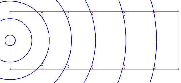
note: This is a over simplified schema for underestanding purpose, reflections (on objects and walls) and frequency wavelength will affect it.
Composed Sources
In audio, a composed source refers to sound originating from multiple, distinct primary locations that combine to create a single perceived auditory event. These individual locations act as single primary point sources, each radiating sound waves. The combined effect of these waves creates the final characteristic of the composed sound after a certain distance.
- Multiple Primary Point Sources: Unlike a single-point source where sound originates from one location, a composed source involves several sound-emitting points.
- Combined Sound Waves: The sound waves from each individual point source interact and add together to form the final perceived sound.
- Examples: Instruments like pianos, violins, and drums are classic examples. Even a human voice can be considered composed as different vocal tract sections contribute to the overall sound.
Composed Sources in Audio
-
Line Array: A line array functions more like a composed source. It consists of multiple speaker elements arranged in a line. Each element acts as a primary sound source, and their combined radiation pattern creates a specific directivity for the sound. This allows line arrays to project sound over longer distances and control its vertical spread.
-
SBA (Single Bass Array): While named “array,” an SBA often behaves acoustically like a single-point source at low frequencies. It achieves this by strategically placing four or more subwoofers (typically 18" or 21" woofers) on the front wall at approximately 20% of the distance from the room boundaries (walls, ceiling, and floor). This configuration creates a rectangular virtual source that radiates low frequencies in a plane-wave radiation, more uniformly than a single subwoofer.
For sound propagation purposes, an SBA can be considered as a single source, especially at low frequencies where the wavelengths are large compared to the subwoofer spacing.
Plane Wave Radiation when single source combines:
The near field for an 18" subwoofer is around 3 cm at 30hz. Within this zone, the sound behaves chaotically. Beyond the near field (around 3cm), the wavefront transitions into a spherical pattern.
Even though a line array and SBA behave like a composed source, each individual speaker element within the line array will still have its own near field region. This is because the near field depends on the size of the individual element and the wavelength of the sound it produces.
As the spherical waves propagate further, they combines in Far Field in a way that creates a plane wave radiation pattern, creating a Fresnel zone outside and after the near field, but not as an instantaneous process.
-
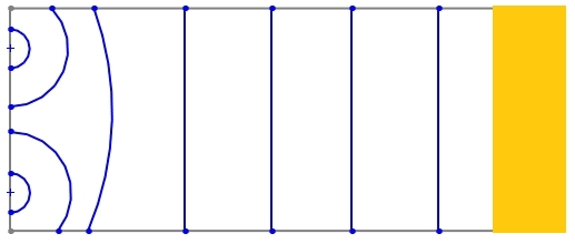
In the case of an SBA, the strategic placement of subwoofers creates a larger virtual source compared to a single subwoofer. This larger virtual source, combined with the influence of walls in a room (as seen in “Walls effect”), contribute to a more persistent planar wavefront behavior at low frequencies within the listening area.
Here with a absorbing materials at rear wall for absorb incoming wavefront from front wall:
-
Line arrays, due to their length, will also exhibit a planar wavefront within a certain distance (defined by the Fresnel zone and line array length). However, this planar behavior weakens as the distance from the line array increases, and the wavefront transitions back to a more spherical pattern.
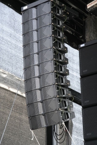
Additionally, it’s important to remember that even these planar wavefronts are not perfect. If a plane wave encounters an object like a sofa, it will diffract, or bend, breaking the plane wavefront and leading to a more complex wave pattern.
In the case au SBA and in more than we have said upper, asymetrical room will not allow a true SBA plave wave front behavior.
DBA
A Distributed Bass Array (DBA) leverages an opposed second SBA to nullify pressure waves generated by the first main SBA.
This cancellation, achieved through phase reversal and delay, effectively reduces low-frequency reflections within the room, leading to improve modal regime and modes.
Here is a simplified representation of wave interference. The blue wavefront represents the original wave, while the red wavefront represents a wave introduced to cancel it:
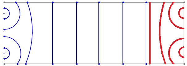
This approach targets low frequencies and doesn’t participate to overall pressure level, the DBA cancellation system works up to 80/100hz in optimal acoustic conditions (obstacles).
The system consumes some SPL pressure so at very low frequency it may be interesting to stop the cancellation DBA effect and use all the subwoofers in phase with delay to maintain SPL, depending on room gain and acoustics.
A suffisent absorbing material on a significant deep (at least 80cm) on rear wall will aslo bring a fair enought reduction of this incoming wavefront as seen with SBA.
Wavefront Behavior and Diffraction
The wavefront travels at the speed of sound, which is constant in a given medium.
The edges of the wavefront are always perpendicular (90°) to the profile of the source.
This schema just show the theory:
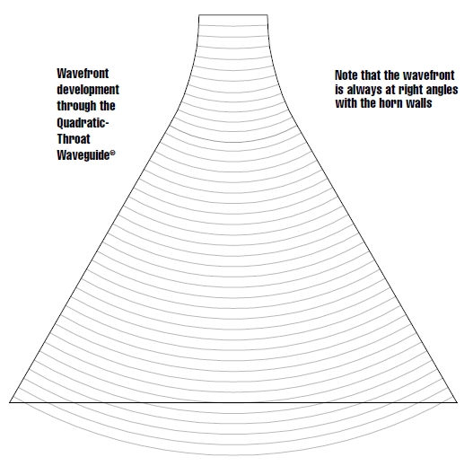
However, sudden changes in the source’s profile, like the end of a horn or the baffle itself, can disrupt this ideal behavior and cause diffraction.
Diffraction is the phenomenon of sound bending around obstacles or edges. In loudspeaker design,
it can occur when sound waves encounter the end of a horn, the edges of the cabinet, or other abrupt changes in the source profile.
This bending of the wavefront can distort the sound and affect the on and off axis frequency response of the loudspeaker, introducing unwanted effects like:
Midrange narrowing: Describe here, A very large dip in the frequency response on and off axis in the midrange frequencies.
Beaming: The concentration of sound in a specific direction, often at the expense of sound radiating in other directions.
To minimize these issues, loudspeaker designers strive for smooth transitions in the source profile to avoid creating sharp edges or mouth that can cause significant diffraction.
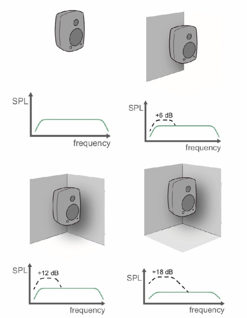
Radiation Space and “room gain”
Radiation space is a solid angle that characterizes the measurement context:
- 4π: whole sphere, measurement without a wall (on a mat for example)
- 2π: hemisphere, so one wall considered infinite
- 1π: quarter sphere, so two walls considered infinite
- 1/2π: 1/8 of a sphere, so 3 walls considered infinite
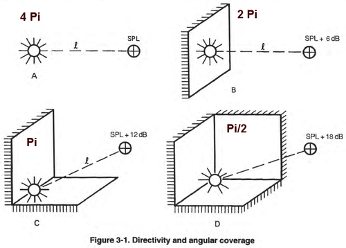
It will impact “low loading” of the speaker :
Additional Information
- The speed of sound in air is approximately 340 meters per second (m/s).
- The wavelength of sound (so called Lambda: speed of sound/Frequency) is inversely proportional to its frequency.
Appendix: Transition Distance Formula
For a circular radiating surface:
Zf = (2 * D^2) / λ
Where:
- Zf is the distance to the beginning of the Fraunhofer zone (meters)
- D is the diameter of the radiating surface (meters)
- λ (Lambda) is the wavelength of the sound (meters)
For a rectangular radiating surface:
Zf = (2 * a^2 * b^2) / (λ a + λ* b)
Where:
- Zf is the distance to the beginning of the Fraunhofer zone (meters)
- a is the length of the radiating surface (meters)
- b is the width of the radiating surface (meters)
- λ (lambda) is the wavelength of the sound (meters)
Calculating Lambda:
λ = c/F
Where:
- F is the frequency of the sound (Hz)
- c is the speed of sound (approximately 340 m/s in air)