The Center-to-Center Conundrum: Why Distance Matters in Speaker Design
Introduction
When it comes to crafting the perfect speaker, meticulous attention is paid to every detail, from the materials used to the precise arrangement of the drivers.
One crucial factor, often overlooked, is the center-to-center distance between the acoustic sources.
When two sources operate in the same frequency range, their relative spacing and phase relationship determine how their sound waves interfere. In a loudspeaker, this interaction becomes particularly important around the crossover region, where the woofer and high-frequency section both contribute to the radiation.
The result is a vertical radiation pattern that can contain lobes and cancellations, commonly referred to as vertical lobing.
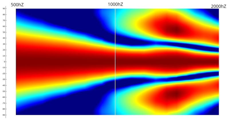
However, vertical lobing is only one of the phenomena that shape the vertical response of a loudspeaker. Other effects, including source directivity, floor bounce and diffraction, will also modify the response in the same vertical plane and sometimes over overlapping frequency ranges. Understanding center-to-center spacing therefore requires looking at the complete vertical behavior of the system.
Understanding Vertical Lobing
Vertical lobing results from the interference between the acoustic sources around the crossover region. When both sources radiate significantly, their contributions combine differently depending on the listening angle, creating the familiar lobes and cancellations in the vertical radiation pattern.
The larger the center-to-center distance relative to the wavelength, the closer the first cancellation moves toward the acoustic axis. This makes the vertical directivity increasingly irregular around the crossover. The exact result also depends on the crossover frequency and slopes, relative phase, acoustic offset, and the directivity of the two sources.
A center-to-center spacing of around 66% of the crossover wavelength is often used as a practical guideline to keep the first vertical cancellation outside the main listening window. This figure should not be taken as a universal optimum or a strict limit. The actual result depends on the crossover design, the relative phase and directivity of the sources, as well as the listening geometry.
This is why center-to-center distance cannot be considered on its own. It always has to be related to the wavelength at the frequency where the two sources overlap.
Vertical Directivity and the Room
The vertical radiation pattern also determines how much acoustic energy is directed toward the floor and ceiling, compared with the energy radiated toward the listening position.
The direct field is the sound that reaches the listener directly from the loudspeaker, while the reverberant field is the sound that reaches the listener after reflections from the room. Both contribute to what we hear, including when listening directly on-axis: the two fields combine at the listening position.
This means that the vertical radiation pattern also contributes to the overall balance between direct and reflected sound in the room. A change in vertical directivity changes how much energy is sent toward the floor and ceiling, and therefore how much of that energy is later returned to the listening area through reflections
The Perception of the Sources Blending Together
There is another aspect related to center-to-center spacing that should not be confused with the vertical polar pattern itself: the perceived blending of the two acoustic sources.
The perception of a “point source” comes from the coherent summation of sound waves from the different sources. This depends on their physical separation relative to the wavelength at the crossover frequency, but also on the listening distance.
The sensation that the woofer and high-frequency section form a single coherent source therefore changes with listening distance. A system heard at 1 meter does not produce the same spatial impression as the same system heard at 6 or 30 meters. As the listening distance increases, the relative spatial separation of the sources becomes less apparent.
This is a different aspect of the same source interaction. The previous section dealt with how the two sources shape the vertical radiation pattern; here, the question is how their spacing is perceived at the listening position. The center-to-center distance, crossover frequency and listening distance all contribute to this perceived fusion, while the crossover slopes, phase relationship and directivity of the two sources also affect how they combine.
The main parameters to consider are therefore:
- Center-to-center distance relative to the crossover wavelength
- Listening distance
- Crossover slopes and phase relationship
- Directivity of the two sources
The same physical spacing can therefore be perceived differently depending on how the loudspeaker is used. Center-to-center distance alone is not enough to describe the perceived blending of the two sources.
Floor Bounce
Floor bounce is a vertical loudspeaker-room interaction caused by the combination of the direct sound from the loudspeaker and a reflection from the floor.
The floor reflection can be represented acoustically by a virtual image source located below the floor. The reflected path is longer than the direct path, creating a time delay between the two signals. This typically produces a cancellation in the lower-midrange region at specific listening positions.
The frequency of this cancellation depends on the geometry, including the loudspeaker height, listening height and distance from the loudspeaker. It is therefore not a fixed frequency, and the cancellation is only observed at specific positions in the room.
The Diffraction Impact
When using a low crossover with closely spaced components, vertical lobing can be reduced. However, diffraction can still be present, especially in small loudspeakers, and will affect the vertical polar response.
The physical presence of the woofer inherently affects the propagation of the higher-frequency wavefront.
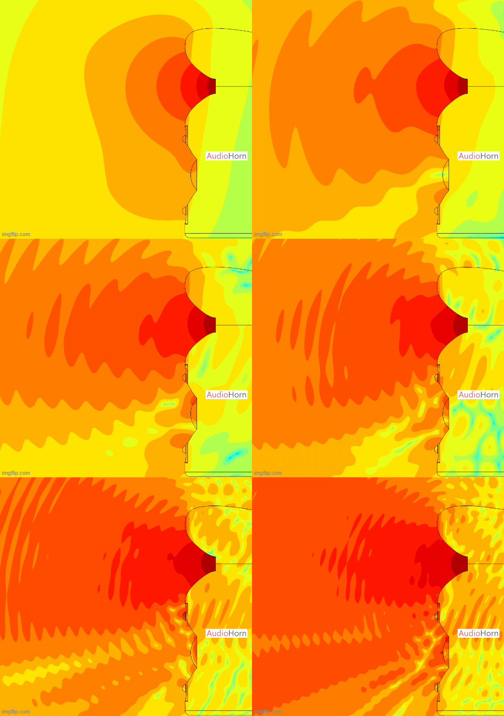
At higher frequencies, the wavelength becomes short compared with the dimensions of the surrounding structures. The woofer, baffle, surround and other physical features can therefore act as obstacles to the wavefront and generate diffraction.
This effect is particularly important when the high-frequency source is positioned close to another physical structure.
It is also relevant to coaxial and Multi-Entrance Horn (MEH) designs. In these configurations, surrounding structures can be positioned very close to and symmetrically around the acoustic source. This symmetry, combined with the close proximity of the surrounding structures, concentrates their interaction with the propagating wavefront, making the resulting artifacts more pronounced, particularly when the surround and/or other nearby obstacles are not smoothly shaped. These concentrated artifacts further affect the directivity.
The polar responses of these systems can be seen in the MEH and coax sections of our MTM, 2.5 or 3 voices article.
This behavior is detailed in our article dedicated to diffraction, particularly in the “Diffraction on Woofer” section.
MTM Configuration: A More Complex Directivity Problem
The MTM (Mid-Tweeter-Mid) configuration introduces another directivity problem. The two mid-woofers form an acoustic source pair of their own, with their center-to-center spacing determining the vertical directivity they produce.
For the combined MTM system to maintain a vertical directivity similar to that of the tweeter or horn through the crossover region, the spacing between the two mid-woofers must remain small compared with the wavelength. In practice, the physical spacing required is difficult to achieve at the crossover frequencies typically used in MTM systems. The two woofers therefore develop a pronounced vertical lobe before their combined directivity can match that of the high-frequency source.
A 2.5-way crossover does not simply remove this problem. By progressively attenuating one of the two woofers, it changes the interaction between the sources, but the remaining woofer-to-tweeter interaction and the woofer-to-woofer interaction occur at different spacings and therefore produce different vertical lobes. These lobes will appear at different frequencies and combine to create a large region of irregular vertical response around the crossover region, which can result in an empty-sounding midrange.
The TMM configuration, where the tweeter and one mid-woofer are placed together and the second mid-woofer is progressively attenuated, is another approach that can reduce some of these interactions.
We cover this subject in the dedicated article: MTM, 2.5 or 3 voices ?.
Horizontal Lobing
Placing multiple acoustic sources horizontally introduces horizontal lobing.
The same interference principle applies, but the resulting lobes and cancellations now occur in the horizontal radiation pattern.
In some loudspeaker designs, horizontal spacing between sources can deliberately be used to shape the directivity. However, the resulting pattern is highly dependent on frequency, spacing, phase and the individual directivity of the sources.
The closer the sources are relative to the wavelength, the wider the useful combined radiation pattern can remain.
Precise simulations should therefore be used when multiple sources are intentionally combined to obtain a specific directivity pattern.
We also address this point in our MTM, 2.5 or 3 voices article.
Perfect Vertical Alignment
Vertical alignment between the high-frequency section and the mid-woofer section is another important parameter.
The acoustic centers of the two sources do not necessarily lie on the same physical plane. Their relative acoustic position introduces a phase difference that varies with listening angle.
If the sources are not properly aligned, this phase relationship can produce additional interference and shift the position of lobes and cancellations.
This is why time alignment and physical acoustic alignment should be considered together with center-to-center spacing.
More information about acoustic centers and apparent apex can be found in our sources below, as well as in our article on delay and phase.
The Takeaway and How to Fix It?
Center-to-center spacing is an important parameter in loudspeaker design, but it cannot be considered in isolation.
The relevant quantity is the spacing relative to the wavelength in the frequency range where the acoustic sources overlap.
A practical design therefore considers:
- Center-to-center spacing: The spacing should be small enough relative to the crossover wavelength to keep unwanted vertical lobing outside the intended listening window.
- Crossover frequency: A lower crossover increases the wavelength and reduces the relative acoustic separation between the sources.
- Crossover slopes: Steeper slopes reduce the frequency range over which the two sources strongly overlap, although the resulting directivity still depends on their phase and individual radiation patterns.
- Time and acoustic alignment: Aligning the acoustic sources controls the phase relationship at the chosen reference position and changes the resulting interference pattern.
- Source directivity: The directivity of each source should be considered because two sources with very different radiation patterns do not combine in the same way as two ideal omnidirectional sources.
- Listening distance: The spatial relationship between the sources changes with listening distance and affects how their radiation is perceived.
The often-used guideline of approximately 66% of the crossover wavelength can be useful as a starting point, but it is not a universal requirement. The final result should be evaluated from the actual acoustic geometry, crossover response and intended listening window.
Vertical lobing should also be considered in perspective. Our hearing is generally less sensitive to vertical than horizontal changes in directivity, so a given irregularity in the vertical plane is not necessarily perceived in the same way as the same irregularity horizontally.
Ultimately, the vertical response should be considered as a complete system response rather than as a simple consequence of driver spacing.
Center-to-center spacing determines one important part of this behavior, but the final response also results from the interaction of source directivity, crossover behavior, acoustic alignment, diffraction and the room itself.
Measurements and simulations remain the most reliable way to verify the resulting directivity.
Sources
- John Vanderkooy & Stanley P. Lipshitz - Power Response of Loudspeakers with Noncoincident Drivers: The Influence of Crossover Design - Journal of the Audio Engineering Society, April 1986
- David J. Murphy - The Directivity Patterns of Loudspeaker Systems - 5th AES Convention, March 1995