Directivity Match: Horns, Waveguides, and Woofer Harmony
Demystifying Directivity Match
In the world of loudspeaker design, achieving a seamless transition between different driver components is crucial for optimal sound quality.
This article delves into the intricacies of directivity matching between horns or waveguides, and woofers, a process that ensures a cohesive and natural listening experience.
The Importance of Directivity Match
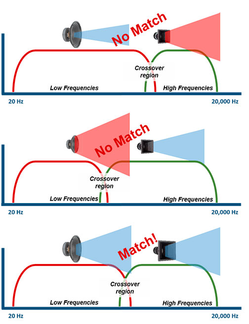
When designing a loudspeaker that combines a woofer with a horn-loaded or waveguided high-frequency driver, one critical aspect is matching their directivity patterns around the crossover region.
Each direct radiation driver has its own transition frequency, the frequency at which the loudspeaker’s directivity changes from wide (omnidirectional) dispersion to narrower, more focused dispersion due to the physical size of the source. This transition frequency is roughly estimated by the formula f = c / (2πR), where R is the effective radiating radius.
Understanding Cone Radiation Directivity
There are two main stages of diaphragm – or cone driver – behavior as frequency increases: pistonic motion and non-pistonic motion.
At low frequencies, the diaphragm moves uniformly in pistonic motion, radiating sound broadly and evenly.
As frequency rises, the size of the radiating surface becomes comparable to the wavelength, causing phase differences (delays) between the diaphragm center (driven by the voice coil) and its edges. These phase shifts lead to a progressive narrowing of directivity.
This transition from pistonic to non-pistonic motion primarily results from geometric and wave propagation effects across the diaphragm surface, and it occurs even if the diaphragm material were perfectly rigid.
Material properties like stiffness and damping can also influence diaphragm behavior but have a lesser impact on directivity compared to the geometric phase effects.
This narrowing of directivity is the reason why the crossover to the high-frequency driver is usually placed around that frequency, so that both drivers have matching directivity for a smooth sound transition.
The size and shape of the baffle also affect this directivity transition.
This transition frequency f_transit can be approximated by:
f_transit ≈ c / (2 π R)
where c is the speed of wave propagation in the diaphragm material, and R its radius.
Why Directivity Match Matters
At the crossover frequency (close to the transition frequency), the directivity of both drivers should ideally match to ensure a smooth spatial response.
Without this match, response dips appear off-axis, degrading the coherence of the reproduced soundstage.
Even when listening on-axis only, the reverberated energy — shaped by off-axis radiation interacting with room acoustics — plays a significant role in the perceived sound.
This is because, at typical listening distances around the critical distance, the sound reaching the listener is approximately a 50/50 mix of direct sound from the speaker and reverberated sound reflected by the room.
If the woofer’s directivity narrows too much in the crossover region, it emits little energy off-axis in that frequency range. As a result, the room receives less energy in this midrange band, creating an energy dip in the perceived sound and a sensation of an “empty midrange.”
This interplay between directivity and room reflections makes directivity matching crucial for natural tonality, clarity, and spatial coherence.
Acoustic Center Distance
Another key factor is the physical distance between the acoustic centers of the woofer and the high-frequency driver.
Ideally, this spacing should be less than or equal to 66% of the wavelength at the crossover frequency — a topic we cover in more detail in our vertical lobing article.
Minimizing this distance helps maintain vertical consistency, reducing lobing artifacts and further reinforcing the perception of a seamless transition between drivers.
Empty Midrange Feeling
Some mid-woofer drivers, such as those from PURIFI, have excellent distortion performance. This often makes it tempting to push their usable range higher than usual.
However, as previously discussed, a woofer’s directivity narrows as frequency increases.
For example, an 8-inch woofer becomes too narrow in dispersion after around 1200–1300 Hz to blend properly with a wide-dispersion device like an AMT or a direct-radiating tweeter.
Using such a crossover point leads to a poor directivity match: at crossover, the tweeter still radiates energy widely off-axis, while the woofer no longer does.
The result is a significant mismatch in how sound is distributed in space.
This isn’t visible in the on-axis frequency response but becomes obvious in polar plots and, more importantly, audible in the room.
It can produce what many describe as an “empty midrange” — not because those frequencies are absent on-axis, but because the woofer no longer emits energy off-axis in that range.
As a result, the room does not reflect those frequencies back to the listener as it does for lower or higher bands, creating a dip in perceived energy and listener envelopment in the midrange.
In other words, it’s the interaction between the woofer’s narrowing directivity in the crossover region and the room’s reflective field that creates this perceptual gap.
Using Midrange Narrowing for Directivity Matching
Principle
A 90° horn should ideally be crossed over at the point where it begins to lose pattern control, typically when its coverage widens toward approximately 100–110°.
At this frequency, the horn no longer maintains its nominal directivity and its radiation widens.
In most practical cases, the natural directivity of a woofer is still too wide at this frequency to match the horn’s dispersion. Its natural narrowing with frequency helps improve the match, but is not sufficient on its own.
To achieve proper directivity matching, we use the midrange narrowing introduced by the baffle, correctly positioned in frequency, to shape directivity at crossover and better align the woofer with the horn’s widening pattern.
The midrange narrowing is not the driver’s natural behavior; it results from interference caused by diffraction at the baffle edges, where delayed secondary wavefronts interfere with the direct radiation and partially cancel it, depending on frequency and geometry.
This concept specifically applies to 90° or narrower designs and is not intended for wide-dispersion HF devices such as 120° horns or similar systems, where the strategy differs fundamentally.
In such cases, the design objective is reversed: instead of narrowing woofer directivity, the goal is typically to broaden it.
Driver considerations
This approach applies specifically to woofers and mid-woofers, which are not used in the high-frequency range and therefore do not inherently suffer from midrange beaming.
For horns, midrange narrowing must instead be minimized or eliminated.
Woofer directivity and cabinet width
The directivity of a woofer naturally narrows as frequency increases, as the radiating diameter becomes comparable to the sound wavelength.
This transition can be reinforced and better positioned in frequency by the enclosure itself.
A cabinet that is just wide enough to accommodate the woofer introduces a midrange narrowing at a predictable frequency range.
When this narrowing coincides with the woofer’s natural directivity transition, it helps shape the polar response so that it smoothly meets the horn’s controlled directivity at crossover.
Importance of controlled narrowing placement
The midrange narrowing introduced by the baffle step behaves like a broad, low-Q directivity shaping that must be properly aligned with the crossover region.
When the enclosure becomes large enough relative to wavelength, it behaves as a half-space (180°) radiator over its baffle width. This boundary condition modifies the radiation space in which it occurs by enforcing a half-space (180°) acoustic field, which alters the distribution of radiated energy in the forward hemisphere.
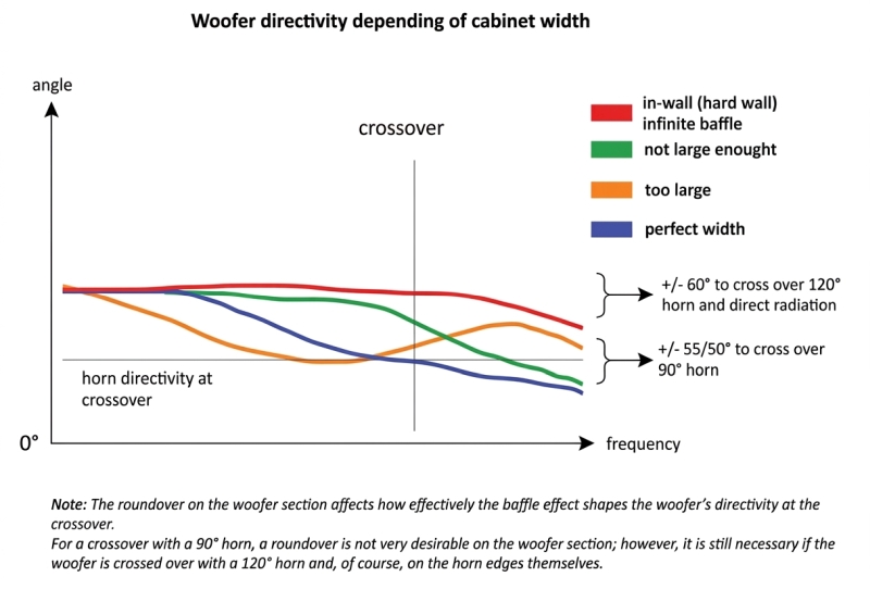
This combination of both effects with the woofer’s natural directivity evolution can, depending on baffle size, lead to a local re-expansion of the apparent radiation pattern (in orange):
-
If the baffle is slightly too wide (orange), this narrowing is still present but shifted too low in frequency, leading to a mismatch at crossover, with a tendency toward a slight widening just above the narrowing region, due to a local half-space (180°) radiation not compensated by a midrange narrowing that occurs too low in frequency.
-
If the baffle is too narrow (green), the narrowing occurs too high in frequency, resulting in less well alignment with the horn’s directivity.
-
In the limit of a very large or infinite baffle (red), the transition behavior is effectively dominated by half-space conditions. Without the EQ-like shaping effect, the expected narrowing cannot properly establish itself in the crossover region, resulting in an overly broad radiation pattern.
-
Conversely, a well-proportioned enclosure (blue) enables a smooth and progressive narrowing that aligns with the horn’s intended coverage.
This discussion assumes a controlled waveguide or horn with a target directivity of around 90° or narrower. For wider radiation patterns (e.g. ~120°) or near-uncontrolled direct radiation, the optimization strategy changes, typically involving a reduced woofer diameter and cabinet edge roundovers to minimize diffraction effects, which, as we have seen in 90° waveguide designs, are desirable as a tool for directivity shaping of the woofer at the crossover, but less desirable in wider radiation patterns.
Conversely, a well-proportioned enclosure allows:
- the woofer’s directivity to narrow progressively,
- the midrange narrowing to occur at the intended frequency,
- a smooth and continuous directivity transition at crossover.
The Wide Perfect Match: A Myth?
The pursuit of a wide directivity match on all the bandwidth at all frequencies, can be a misguided approach.
The crossover slope, along with meticulously adjusted time delays, plays a vital role in ensuring a smooth transition between the woofer’s coverage and the horn/waveguide’s coverage. This transition should be free of abrupt changes (on-axis or off-axis) to avoid unwanted coloration or distortions in the sound.
Moreover, a common misconception in modern loudspeaker design is prioritizing an exact 120-degree directivity match at crossover and with all frequencies on the depends of more important aspects like coverage adapted to listening distance.
This “one-120°-coverage-fits-all” approach leads to completely ignores psyckoacoustics principles and coverage adapted to distance as see in critical distance article.
Improved Directivity with Round-Over Returns
Our horns incorporate a design element called a “round-over return.” This feature enhances directivity control by mitigating the narrowing effect call midrange narrowing/beaming that occur in the midrange frequencies.
The round-over return is a smooth, curved transition that seamlessly follows the horn’s profile until it meets the side of the enclosure. This design minimizes disruptions to the wavefront, preventing unwanted narrowing of the sound dispersion pattern in the midrange.
Benefits of Round-Over Returns:
-
Improved Directivity: By eliminating midrange narrowing, the round-over return ensures a more consistent and predictable directivity pattern across the entire frequency spectrum.
-
Smoother Sound Transition: The smooth curvature of the return minimizes potential phase cancellations and contributes to a more natural and seamless transition between the horn and the enclosure.
-
Enhanced Off-Axis Response: The improved directivity control translates to a more consistent tonal balance thanks to coherent power response (the fusion of direct and reverberated field as seen upper), for listeners positioned both on and off-axis from the speaker.
Directivity Matching Between Horns: A Different Approach
When dealing with multiple horns or waveguides in a loudspeaker design, the crossover approach differs slightly. Here, the ideal crossover point is not where each component loses its directivity, but rather where both maintain a constant directivity pattern.
This constant directivity should be maintained not only at the crossover frequency but throughout the crossover overlap range.
Following these principles of directivity matching ensures a natural and cohesive sonic experience for the listener, free from unwanted artifacts and with a smooth transition between different driver components within a loudspeaker.
![]()