How to implement my horn and my speaker
Acoustic Basics Summary
Energy is not free, so when we ask a compression driver to maintain constant directivity in a horn, the on-axis response will always take the shape of a bell curve, requiring equalization (EQ) using digital signal processing (DSP).
The implementation of a speaker is not done according to the room. The entire speaker must be flat on-axis when measured at close distance—approximately three times the width of the front baffle, or even closer if room acoustic interferences are too strong at that distance.
Air absorption and room acoustics will then naturally cause a decay. This decay must NOT be corrected at the listening position—never.
Room modes below 100 Hz, when taking into account a listening area (not a single point), can be EQed—but nothing more.
All steps described here must be done in the correct order using REW and a measurement mic.
FIR & IIR
A FIR filter can do minimum and linear phase filtering; an IIR can only do minimum phase filtering.
Linear phase filtering (enabled by FIR DSP with taps, which is costly in CPU resources) doesn’t alter the phase, so it’s great for crossovers but not ideal for frequency correction, where we actually want to alter the phase along with the magnitude.
When using it for crossover, the most straightforward method is to EQ the driver flat about 1 octave beyond the intended crossover frequency using minimum phase filtering (to ensure correct magnitude and phase response), then apply a linear phase crossover filter. This preserves phase alignment at the crossover point while keeping the overall response controlled.
Minimum phase filtering (available with IIR DSP) alters the phase, so it is very well suited for frequency response correction.
When using a controller without linear phase capability, we will in most cases try to combine the driver’s natural acoustic roll-off with the DSP’s electrical cutoff. We’ll see this type of application later in the article.
As the acoustic emission point is not at the same depth between drivers, we usually need to delay the woofer to maintain in-phase summation and avoid cancellation at the crossover point.
The steeper the slope, the more critical the delay alignment between components becomes—so be careful with this and refer to the dedicated paragraph in this article, especially since a very accurate delay also reduces the overlap region and helps avoid pre-ringing near the crossover.
If the applied delay is spot-on, the best result is obtained using an LR150dB FIR crossover, following IIR linearization (1 octave below the crossover point for the compression driver, 1 octave above for the woofer).
Crossover Slope
A crossover slope, expressed in dB per octave, indicates how quickly the signal level decreases outside a driver’s intended frequency range. A steeper slope attenuates frequencies more rapidly, while a gentler slope allows a more gradual transition between drivers.
A stronger or gentler crossover between a horn and a woofer allows controlling how much each driver operates outside its optimal frequency range. Drivers should not be pushed too far beyond their ideal band.
Gentler slopes create a wider overlap region, which is more forgiving of differences in directivity between the drivers, though it allows each driver to operate slightly outside its ideal range.
When the overlap is reduced but not extreme, any mismatch in directivity will become more noticeable, potentially causing irregularities in the off-axis response.
On the other hand, very steep slopes confine each driver almost strictly to its band, minimizing off-band operation. However, they require extremely precise delay and alignment; otherwise, a very localized and abrupt response anomaly will appear at the crossover region where the slopes overlap — mostly off-axis, but sometimes even on-axis if the delay is significantly wrong.
Determining an exact slope value is difficult, as many parameters affect the result, but a 48 dB slope is generally considered effective when drivers have a good directivity match, using either IIR or FIR filters.
Ultimately, selecting the crossover slope is always a matter of balance.
Polar Plot
A polar plot describes the off-axis behavior of a loudspeaker by showing how sound level varies with angle around the device. It is used to visualize the directivity pattern in a given plane (vertical or horizontal).
It is typically obtained by measuring the loudspeaker at fixed angular steps (e.g. every 5 or 10 degrees), while rotating the loudspeaker on itself with the microphone kept in a fixed position.
Measurements are taken at a defined distance (often around 1 m in non-anechoic conditions), with the setup (mic and speaker) positioned as far as possible from any reflective surfaces, and using gated processing to reduce room reflections and ensure cleaner directivity data.
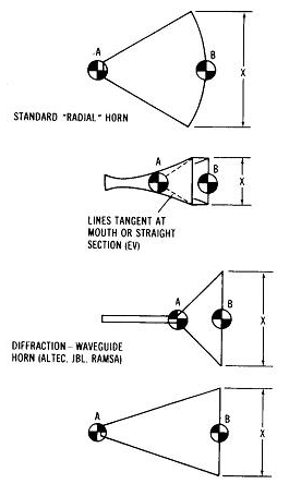
APEX
For horn-loaded systems, polar measurements are performed by rotating the loudspeaker around a fixed reference point called the apparent apex.
The apex is not a physical acoustic source and does not correspond to the acoustic center of the loudspeaker (used for time alignment and delay compensation). It is a practical virtual reference point, located near the horn geometry, used to describe the apparent origin of the radiated wave once it has been transformed by the horn.
Using this point as the rotation axis allows near-field polar measurements (e.g. at 1 m) to better approximate far-field behavior. If the apex is not respected, a so-called directivity distortion appears: the polar response changes with distance, leading to strong divergences as measurements are taken closer to the speaker.
Referencing the horn to the apex provides a consistent geometric origin for angular measurements and is therefore critical, especially at short distance, to maintain stable and representative directivity data.
Klippel Near-Field Scanner
The Klippel Near-Field Scanner (NFS) uses a different approach. Instead of rotating the loudspeaker, the microphone is moved precisely around it.
In this case, the system knows the exact 3D position of the microphone for each measurement point and uses this data to reconstruct the sound field mathematically, typically through spherical harmonic expansion (a solution of the Helmholtz equation). This allows the software to derive the far-field response and polar maps from near-field measurements.
This approach is fundamentally different from classical polar measurements.
It should not be reproduced manually: moving the microphone in a standard setup without this reconstruction process will lead to incorrect polar data.
More information on how to perform a polar map can be found in our Polar measurement article.
1. The Horn with DSP
We have to choose where to do our crossover—basically, it’s when the horn starts to lose directivity control but still has enough SPL in its low-frequency region.
A factor to consider is the physical distance between the acoustic centers of the woofer and the high-frequency section. Ideally, this distance should be less than or equal to roughly 66% of the wavelength at the crossover frequency. However, listening distance also plays a role. At greater listening distances, the impact of this spacing becomes less critical, as explained in the vertical lobing article.
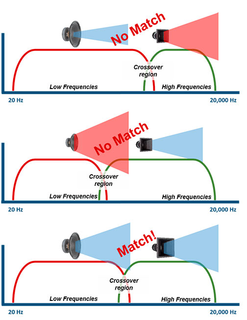
The directivity of two crossed-over elements must be similar at the crossover frequency, as detailed in the directivity match article.
If people mainly listen while sitting, the center of the horn should be around ear height, roughly 94–96 cm from the floor.
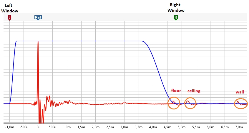
Measure the horn at 30–60 cm (depending on woofer or horn size) to capture its complete acoustic behavior and response (including baffle/roundover integration)—but without including the room.
We gate the measurement before the first reflection visible on the impulse response to avoid including room reflections in the response – see pictures below.
EQ it flat using minimum phase filtering, not linear phase, from the lower frequency roll-off up to the breakup frequency.
Using minimum phase filtering in IIR will also allow us to correct the phase simultaneously and effectively:
-
Minimum phase filtering modifies the phase response correspondingly to frequency changes; for example, a dip or peak in frequency response is accompanied by a related phase shift. An IIR EQ thus corrects both frequency and phase responses simultaneously, which is necessary to linearize the overall response effectively.
-
FIR filtering (linear phase filtering) must only be used for crossover applications. When performing a crossover, the goal is to cut the frequency response without altering the phase, which is exactly what FIR filtering achieves. Therefore, FIR is suitable for crossover filtering but not for EQ corrections.
Sometimes, the breakup impact on the frequency response is so pronounced that it’s not possible to EQ flat up to 20 kHz. In this case, it is better to EQ flat only up to 14–15 kHz, as it is unnecessary to “excite” a diaphragm breakup.
minimum phase filtering (IIR)
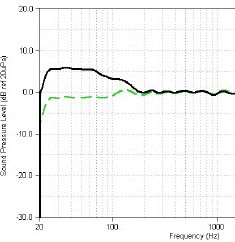
We can add with REW a target curve, like a LR 48:
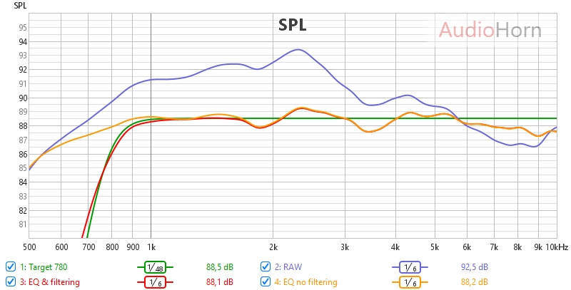
We use EQ to achieve a flat frequency response down to the point where the horn’s natural roll-off begins.
Then, minimum-phase filtering is applied to shape this natural roll-off (green) and match a desired target curve (red).
In DSP, this filtering acts as an electronic adjustment that combines with the horn’s inherent roll-off to produce the final acoustic response. For example, applying a Linkwitz-Riley 48 dB/octave (LR48) filter to a flat response will result in an acoustic LR48 cut. However, if the initial response is already sloping downward, the same LR48 filter will have a different acoustic effect.
In practice, the filter’s cutoff frequency and its electronic characteristics interact with the horn’s existing roll-off to determine the final acoustic response.
Another approach is to apply EQ to create a flat response extending one octave below the desired cutoff frequency, and then apply the filter. In IIR implementations, this method can be costly in DSP resources and may be limited by the processing power available. However, it allows the electronic filter’s effect to closely match the resulting acoustic cut by compensating for the horn’s natural roll-off in the region of interest, enabling more predictable filter operation.
Linear Phase Filtering (FIR)
To achieve accurate acoustic linear phase filtering, a two-step EQ process is recommended.
First, equalize the drivers using minimum-phase filtering to target a flat response one octave below the crossover frequency. This step intentionally manipulates phase to achieve the target response.
Then, apply a steep cutoff filter (up to LR 150) using linear-phase filtering; this filter does not manipulate phase.
Implementing a steep cutoff filter precisely is crucial. Delay alignment (point 3) requires meticulous calibration, and pre-ringing can be a valuable diagnostic tool.
Additionally, the final acoustic responses of both sections on either side of the filter must mirror each other. To achieve this mirroring effect, a minimum-phase equalizer applied one octave before the crossover corrects phase response, ensuring the electrical and acoustic cuts align perfectly. This same approach must be applied to the woofer crossover.
Regarding very steep cuts: compared to LR48 filters, LR150 filters offer advantages when approaching distortion limits, reducing the overlap region at the crossover and minimizing pre-ringing, while also improving thermal performance. These steep cuts are often implemented using convolution filters generated by software like RePhase, and require very precise tuning and strict adherence to the process.
2. The Woofer
Basically, we will do the same as for the horn section, with the same choice of filtering strategy.
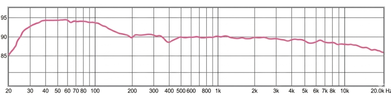
We EQ the woofer flat at 30–60 cm in front of it (so we change the height position of our mic), as we also want the baffle step effect in the measurement.
We cross it at the same frequency as the horn and in the same way. A target curve can be used too, but in most cases, the woofer will naturally rise in frequency, so we only need to EQ it flat one octave above the crossover frequency.
In active filtering with delay, mirroring the high-frequency filter’s response in the low-frequency range is a common technique.
Important: Bring your woofer as close as possible to the horn to reduce the vertical center-to-center distance.
The ideal distance is below 66% of the crossover wavelength (λ = wavelength of the crossover frequency), while keeping the horn’s acoustic center at ear height — typically 94–96 cm for seated listeners. Otherwise, vertical lobes will appear (as explained in the center-to-center spacing and vertical lobing article).
If your woofer response is rising in the box (partly due to baffle step), and only in this case, you can linearize it by adding a simple air-core inductor in series on the “+” of the woofer.
This will reduce H3 distortion by interacting with the motor. It doesn’t work if the woofer uses AIC (Active Impedance Control, like in 18Sound drivers).
It’s one of the most effective tricks in active filtering, explained here: Speaker Break-Up and Associated Distortion.
The inductor value is typically around 1.2 to 1.7 mH.
Then, make a precise EQ at 30–60 cm using gated measurement, but only above the beginning of the modal region, typically around 200–250 Hz depending on the room.
Below this region, room gain progressively dominates the in-room response, so bass alignment must be evaluated from the listening area rather than from close-distance measurements.
In practice, up to ~200 Hz, the microphone should be moved to several positions around the listening area in order to average the room response and base the EQ on this spatial average.
Under ~100 Hz, where room modes usually dominate, you can refer to the subwoofer integration article.
To simulate the inductor network in VituixCAD with both the impedance curve and the frequency response, and to apply precise EQ at the end, we need to measure the woofer including the baffle step effect — but excluding the room.
This means measuring close enough to capture baffle step behavior, and gating the measurement to eliminate room reflections:
Be careful not to have reversed the phase (+ and –); you can verify this by intentionally reversing the polarity, measuring again, and checking for cancellation at the crossover frequency.
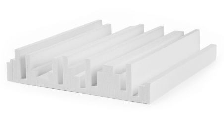
As for bracing and stuffing, you can follow our guide: braces and stuffing.
For vented vs sealed enclosure types, we recommend reading the dedicated section in our subwoofer integration article, which also applies to woofers.
3. Find the Delay Between Horn and Woofer
The reason time alignment (delay adjustment) is required is that the acoustic centers of the drivers are not located at the same physical depth.
Because of this, when both drivers reproduce the same frequency band around the crossover point, their wavefronts do not naturally arrive at the listening position at the same time. This time difference creates a phase offset between the drivers.
If this is not corrected, the two drivers will not sum coherently. This leads to phase mismatch, resulting in peaks and dips in the frequency response on-axis, and irregular interference patterns off-axis.
In the crossover region, this results in uneven vertical lobing, stronger cancellations at certain angles, and an unstable directivity pattern that changes rapidly with position.
Double impulse method
There are several ways to find the delay, but we’ll cover the simplest method here.
Advanced users can explore the sound card loopback method, but the end result is essentially the same.
In your DSP configuration, deliberately add 10 ms of delay to the compression driver to shift its impulse peak forward in time.
Place the microphone at 1.50 m, at an average height between the horn and woofer, and roughly align the SPL levels (we will fine-tune this in the next step).
Keep the frequency correction EQs active, but remove the crossover filters. Then, perform a wide-range sweep around the intended crossover frequency with both drivers playing together.
For example, sweep from 300 Hz to 5 kHz if you’re planning a crossover around 700 Hz.
You don’t need a high volume — avoid damaging the compression driver since it is playing without a high-pass filter.
Observe the impulse response in REW: you should see two impulse peaks — one around 0 ms and another near 10 ms (depending on actual timing).
Now simply subtract the 10 ms you added earlier to find the actual time offset between the drivers. For example:
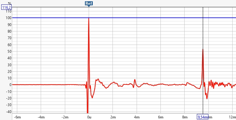
9.54 ms is the delay between the two impulse peaks, so the actual delay offset is –0.46 ms.
At the speed of sound in air, this corresponds to approximately 15 cm.
Apply the correct delay in the DSP to the driver that is closer to the front baffle, and don’t forget to re-enable the crossover filters on each element.
This method provides a close approximation of the correct delay.
However, for precise alignment, we should also check the phase response or time-domain response using a clean, relatively close measurement.
Fine Tuning the Delay
The impulse response method alone identifies the initial delay relative to the time reference T0, but it is insufficient for accurate tuning. Frequencies align with the initial rise of the impulse rather than the T0, creating a natural shift of the impulse peak as wavelengths increase at lower frequencies. This behavior is inherent to the signal and must not be altered.
Using the impulse method, we attempt to mitigate this by selecting a narrow frequency range around the crossover region for both drivers. However, this is not perfect because the impulse peak does not guarantee coherent phase alignment at the crossover point.
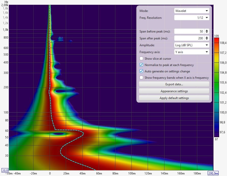
This is why we must analyze the spectrogram (Wavelet, with Y-axis as frequency). By visually zooming in, we can track the time and energy distribution at the crossover. Starting with the initial delay on the tweeter or compression driver, we increase the delay until the transition is vertical and smooth on the spectrogram. Naturally, the frequency response can also be checked to verify the alignment.
The final calculation often reveals that the required delay places the tweeter significantly further back than what pure mechanical geometry suggests. This is not because one driver is inherently “slower” or “faster” —all drivers react at similar microscopic speeds— but because of differences in electro-mechanical parameters that affect the rise time. These are mainly influenced by:
-
Moving mass (Mms): Which affects the driver’s inertia and how quickly it responds to an excitation.
-
Mechanical compliance (Cms) or equivalently total suspension stiffness K: This represents the rigidity of the suspension. It determines the restoring force and how the driver resists displacement.
-
Motor strength (Bl): The “Force Factor” which, relative to the mass, determines the acceleration and control the motor exerts over the diaphragm.
Important Note on the “Bl/Mms” ratio: Contrary to popular belief, a high Bl/Mms ratio does not make a driver “faster” in terms of signal propagation. It will show a difference in sensitivity and damping; a “strong” motor modifies the rise time but will not make a driver “faster”. It is a question of time-domain response (represented by the phase), not “speed” or “impulse quality”.
Note on secondary factors: Other real-world factors contribute to this shift. Voice coil inductance (Le) acts as an electrical filter, delaying current flow before mechanical movement begins. Additionally, the amplifier’s damping factor and the back-EMF govern how strictly the motor is controlled. Finally, conventional crossover filters (Passive or IIR) introduce their own specific group delays and phase rotations. These combined parameters mean the apparent time shift is not a simple latency, but a complex, frequency-dependent phase alignment.
4. Align Levels
With only one speaker playing, place the microphone 1.50 m away, at the average height between the horn and woofer (same position as in step 3).
We will align the dB levels between the two components through iterative measurements.
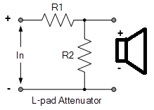
The first attenuation applied to the compression driver — or even a tweeter — in an active filtering system should ideally be passive, in order to protect the high-frequency driver and improve the signal-to-noise ratio.
For this purpose, we use an L-pad network:
Then, refine the level matching in the DSP by adjusting in steps of 0.2 dB, in stereo, with both speakers playing — and without using the measurement microphone — by listening at the actual listening position.
If the sound feels muffled, increase by 0.2 dB and try again. If it sounds too bright or aggressive, reduce by 0.2 dB.
Why in stereo: when both speakers are playing, low frequencies tend to sum more effectively than high frequencies. This behavior must be taken into account for tonal balance.
Perform this step after applying acoustic treatment, as such treatment tends to reduce high-frequency energy.
In practice, we often add an extra 0.2 dB after installing proper absorption (see 7. Acoustic Treatment).
Without acoustic treatment, it can be better to slightly reduce high frequencies, this allows tuning of the overall energy balance in relation to the room’s acoustics. This aspect is easily manageable if the polar response is clean — free of off-axis anomalies, midrange narrowing, or beaming.
Of course, this final step only makes sense if you’ve properly completed all the previous ones.
5. Speaker Position
The acoustic center of the horn must be at the same height as your ears at the listening position.
Generally, this means placing the acoustic center of the horn around 94 to 96 cm above the floor.
You should toe-in your speakers towards your main listening position, like this:
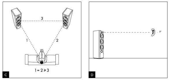
You should also listen to your speakers within the Critical Distance area and avoid placing your listening position too close to the rear wall behind you — leave at least a 1 m gap.
However, this ideal triangle setup is just a guideline.
If you can have about 3 to 3.5 m between speakers and 1 to 1.5 m of space behind your listening position, it will generally sound better than strictly following the theoretical triangle.
6. Subwoofer (optional)
You can see or dedicated article about subwoofer integration and how, depending on listening level, to shape bass level below 200 Hz.
7. Acoustic Treatment
You can read our dedicated article about Acoustic Treatment.
8. Listening Position Tuning And Floor Bounce
As discussed in point 4, certain adjustments can be made at the listening position to fine-tune the SPL (Sound Pressure Level) balance between the low and high frequency ranges (woofer for the lows, and tweeter or compression driver for the highs).
The high-frequency driver’s response may naturally exhibit a downward slope, which varies with distance, horn directivity, and room acoustics.
In some cases, a more pronounced tilt may even help achieve a smoother energy balance—especially with wider-opening horns (e.g., 120°) that can radiate too much energy into the room at longer listening distances, whereas narrower ones (e.g., 90°) generally do not require it, depending of acoustics.
Depending on the floor composition, we may also observe anomalies in the midrange due to floor bounce, caused by floor reflections from the woofer. These reflections vary with microphone or listener position and can be partially addressed with EQ, but it is important to take into account that our auditory system already integrates them in natural listening conditions, since in everyday life we constantly perceive voices and sounds at head height with similar floor reflections.
It is therefore useful to analyze the floor bounce across the listening area. Attention must be paid not to overcorrect it: floor bounce is already part of the natural perceptual processing of the auditory system.
If it is corrected, it should remain light, with a global frequency adjustment (and not a narrow or surgical one), based on several measurements at the listening position.
Except for low-frequency adjustments in the modal region — typically below 250 Hz and intended to address room modes — and, in some cases, mild treatment of floor bounce effects in the low-midrange, no frequency corrections or filters are applied to the main speakers at the listening position.
Generic Target Curves In Living Room
This interplay of room acoustics, listening distance, speaker placement and directivity, and personal taste effectively defines a personalized target curve, shaped by your listening environment and preferences.
It’s important to understand that there is no single, universal “ideal” target curve — and even a personalized one is only valid within a specific configuration, position, and acoustic context.
Even in this region, caution is required, as cancellations due to modal behavior can vary significantly with even small changes in microphone position.
It’s therefore essential to evaluate the listening area as a whole, rather than relying on measurements from a single point, multi-point measurements are useful for identifying modal behavior below 100/150 Hz.
We strongly recommend reading our subwoofer integration guide for more on this topic.
The design and engineering of a speaker must not be based on measurements taken at the listening position, except for the modal region.
![]()