Speaker Breakup and how to reduce its distortion
Introduction
Loudspeakers, despite their crucial role in sound reproduction, can introduce unwanted distortion.
One significant contributor is cone breakup, a phenomenon related to the moving material (diaphragm, cone…) resonating at high frequencies.
This article dives deeper into the science behind cone break-up, its impact on sound quality, and explores filtering techniques to mitigate this issue, focusing on woofer breakup. For compression drivers, we recommend reading our masking effect and audibility article.
What is speaker break-up?
1. Basic operation
When a speaker emits sound, the voice coil, driven by the signal from the amplifier, moves. Since it is attached to the membrane (cone driver) or a diaphragm (compression driver), it pulls the radiating surface along in its movement.
There are three stages of membrane behavior as frequency increases: pistonic motion, non-pistonic motion, and breakup modes, the latter being a more severe form of non-pistonic behavior characterized by modal resonance patterns across the membrane materials.
At low frequencies, the membrane or cone driver moves uniformly in a pistonic motion.
2. Transition from pistonic to non-pistonic motion
As frequency rises, the radiating surface size becomes comparable to the wavelength, causing phase differences across the surface that lead to a progressive narrowing of directivity.
This geometric effect alone occurs even if the membrane behaves like a perfectly rigid piston.
Simultaneously, material properties induce internal wave propagation delays and localized resonances, which affect the membrane’s motion and sound distortion but have a secondary influence on directivity compared to the geometric factor.
These phase shifts between the membrane center (driven by the voice coil) and its edges cause the motion to deviate from pure pistonic behavior, marking the onset of non-pistonic motion. However, this stage does not yet involve breakup or fractionation.
3. Breakup modes and material implications
Breakup modes (or fractionation) arise at higher frequencies, when parts of the radiating surface resonate independently, forming complex modal patterns that depend on the material properties of the membrane.
This results in distortion and irregular radiation distinct from the earlier smooth non-pistonic behavior.
To delay the onset of fractionation, manufacturers can opt for more rigid membranes. However, an ultra-rigid membrane is not ideal, as it can introduce internal vibrational modes, also known as modal resonances.
At certain frequencies, these modes cause localized resonances across the surface of the membrane, where different parts vibrate inconsistently, generating undesirable distortions.
Fractionation is inherent to the mechanical structure of a real membrane.
A more rigid membrane generally pushes the onset of breakup to higher frequencies, while damping helps reduce the amplitude and Q of the resulting resonances. However, stiffness, mass, geometry and damping interact, so increasing rigidity alone does not necessarily result in lower overall distortion.
4. Material strategies and special cases
This is why cone speaker designers often use composite materials and blends to construct membranes. The goal is to strike a balance between rigidity, damping, and weight.
Rigidity can push fractionation to higher frequencies, while damping reduces the energy of internal resonances, thereby limiting distortion and resonance peaks caused by vibrational modes.
For compression drivers, the diaphragm is usually smaller, and its breakup typically occurs outside the ear’s sensitive range, so it’s less of a problem.
Causes of Cone Break-Up
Cone break-up occurs when the loudspeaker cone develops mechanical resonances at high frequencies, causing parts of the radiating surface to vibrate differently from each other instead of behaving as a single piston. Several factors influence these resonances:
-
Dimensions, Thickness, and Shape of the Cone:
The size, thickness, and curvature of the cone significantly impact its resonant behavior. Thinner or less rigid cones tend to break up earlier than stiffer or appropriately curved ones. -
Cone Material:
Different materials possess varying stiffness and damping properties. Stiff materials can push breakup to higher frequencies, but may produce strong resonances if damping is low. Materials with higher inherent damping, such as some treated papers and composites, can help reduce the amplitude of these resonances. -
Boundary Conditions of the Cone:
How the cone is secured to the frame and coupled to the suspension also plays a role. The mechanical boundary conditions influence the frequencies, Q factors and shapes of the resulting modes.
Impact of Cone Break-Up on Distortion
When the cone breaks up, it can strongly amplify distortion generated by the nonlinear behavior of the loudspeaker.
These nonlinearities generate harmonic distortion. For example, a 1 kHz signal will generate a 3rd harmonic at 3 kHz when third-order nonlinear distortion is present. If the cone has a strong breakup mode at 3 kHz, this unwanted 3 kHz component can be strongly amplified by the breakup resonance.
This is an important point: the breakup does not generate the H3 from nothing. The nonlinear behavior of the driver generates the harmonic distortion, while the breakup resonance can strongly amplify the harmonic component when its frequency coincides with the breakup frequency.
For example, when a violent breakup occurs at 1500 Hz, it can strongly amplify the 3rd harmonic generated by a 500 Hz fundamental. This can produce a strong H3 peak around 500 Hz in a conventional harmonic distortion plot, even though the unwanted acoustic component itself is at 1500 Hz.
Therefore, even if the woofer is crossed at 1 kHz, playing a 500 Hz signal can still produce an unwanted acoustic component around 1500 Hz if the driver’s nonlinearities generate sufficient H3 and the cone has a strong breakup mode at that frequency.
Breakup can also introduce time-domain problems and, for compression drivers, out-of-plane wave radiation behavior, especially visible with compression drivers in horns.
Cone Break-Up and Electrical Current
The speaker cone is a mechanical system driven by the electrical current flowing through the voice coil.
At high frequencies, the cone can develop mechanical modes in which different parts of the radiating surface move independently. These modes can be strongly excited by the electrical signal, and the resulting mechanical motion interacts with the electrical behavior of the voice coil.
When the voice coil moves through the magnetic field, it also generates a back electromotive force (back EMF) that opposes the applied voltage. This is an essential part of the electromechanical coupling between the voice coil and the mechanical system.
The mechanical motion of the driver therefore affects its electrical behavior through this back EMF. The electrical current, impedance and mechanical motion are consequently closely interconnected.
The electrical impedance seen by the amplifier therefore becomes important. Increasing the series impedance at the breakup frequency reduces the current available to excite the driver at that frequency.
Inductance and Impedance
An inductor opposes changes in current, and its impedance increases with frequency. Adding a series inductor therefore increases the impedance presented to the woofer at higher frequencies, reducing the current available to excite the driver.
Impedance is not simply electrical resistance: it includes both resistive and reactive components and determines how much current flows for a given applied voltage.
How Increased Inductance Helps
Here’s how increased series inductance can help reduce cone breakup excitation:
-
Limits Current at High Frequencies:
The increasing impedance of the series inductor reduces the current delivered to the voice coil as frequency rises. This reduces the electrical excitation available to the driver around its high-frequency breakup modes. -
Reduces Excitation of Breakup Modes:
By increasing the series impedance around the breakup region, the electrical drive applied to the driver at those frequencies is reduced. This can reduce the amplitude of the associated mechanical modes and therefore the resulting distortion. -
Partial Damping Effect:
This is not a traditional mechanical damping mechanism, but the increased electrical impedance reduces the electrical drive available to excite the mechanical resonance. The resulting effect can therefore be similar to a damping of the unwanted response.
However, it’s important to consider these points:
-
Limited Effect:
Increased inductance alone might not entirely eliminate cone break-up, especially for severe breakup issues. It is a tool that must be matched to the driver’s behavior. -
Frequency Dependence:
The impedance increase due to inductance is progressive with frequency. Its effectiveness therefore depends on the breakup frequency and on the desired operating range of the woofer. -
Driver Dependence:
The resulting distortion reduction depends strongly on the driver’s motor, voice coil, inductance behavior and mechanical modes.
Filtering Techniques for Break-Up Reduction
Several filtering techniques can be employed to address cone breakup and reduce the associated distortion.
Because these filtering techniques rely on modifying the electrical impedance presented to the driver, DSP equalization alone cannot reproduce this mechanism. It can correct the acoustic frequency response, but it cannot create the high electrical impedance needed to reduce the current exciting the breakup mode. A physical series component is therefore required, even when DSP is used for the remaining acoustic equalization.
The result depends on the woofer motor design, but in many cases the main improvement is observed in H3 distortion.
The effect is strongly related to the motor design, voice coil behavior, and inductance characteristics. A lower and more linear inductance can reduce distortion related to inductive behavior, which explains why an impedance-based filtering approach is not necessarily the main solution for drivers where inductance-related distortion is not dominant, such as many compression drivers, tweeters, and drivers incorporating technologies like 18Sound’s AIC.
Each approach has its advantages and limitations.
Series Notch Filters
These passive filters use a combination of inductors (L), capacitors (C), and, where required, resistors (R) to create a high series impedance at the target breakup frequency.
The important point is that the notch network must be arranged so that the high impedance it creates is actually presented to the woofer at the breakup frequency. It is this high impedance that reduces the current available to excite the corresponding mechanical mode.
In a passive crossover with additional parallel branches, the series notch should be placed last in the woofer branch, as close as possible to the driver, so that these branches do not provide a low-impedance path that bypasses the intended impedance rise.
A conventional parallel notch must not be used for this purpose because it behaves differently. It will flatten the acoustic response while presenting a very low source impedance around the notch frequency. Two filters can therefore produce very similar SPL responses while producing very different distortion levels.
This is why the complete passive filter should always be simulated in VituixCAD. The relevant parameter is the source impedance actually presented to the woofer at the breakup frequency.
Here is the H3 of a Dayton RS52 with and without LC notch. The SPL is exactly the same across the whole frequency range, so this is not an SPL-related difference:
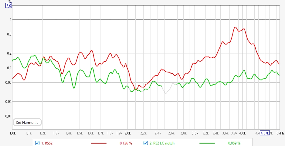
This solution is well suited when the driver already has a flat response in its final enclosure. Otherwise, the next solution may be a better choice.
Passive Crossover Considerations
A passive crossover does not inherently prevent this approach from working. What matters is the source impedance actually presented to the woofer at the breakup frequency.
A complete passive crossover can be designed so that the woofer sees a strong series impedance peak at the breakup frequency. However, other components of the crossover can modify this impedance rise, depending on their topology and position in the network.
In particular, a parallel branch can affect the source impedance presented to the woofer. A component or branch placed in parallel with the woofer does not automatically cancel the effect of a series notch. The important question is whether it provides a sufficiently low impedance path at the breakup frequency to reduce the high source impedance that the series notch is intended to create.
A parallel network can therefore coexist with a series notch, provided that the complete crossover topology still allows the woofer to see a sufficiently high source impedance at the breakup frequency.
The complete crossover must therefore be analyzed as a whole. The relevant parameter is the source impedance actually presented to the woofer at the breakup frequency.
Air Core Inductors with Active Filtering
These first-order filters, in series, often implemented with a single inductor, allow lower frequencies to pass through while progressively attenuating higher frequencies, including those near the break-up point.
This approach offers a simpler design and also linearizes the woofer. It’s the easier solution.
It gradually increases the impedance with frequency and replaces part of the EQ required to linearize the woofer response. This approach works particularly well when the woofer already exhibits a rising response in its final enclosure.
The inductor must be an air core inductor (ex. Mundorf L140) and not an iron core inductor; otherwise, nonlinear magnetic behavior in the core can introduce additional distortion, including H3.
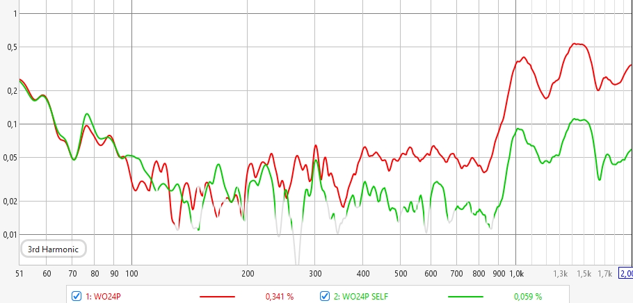
Here is the H3 of a SbAcoustics WO24P with and without an air inductor in series. The SPL is exactly the same across the whole frequency range, so this is not an SPL-related difference:
Compensation Networks
Some compensation networks can be used to address specific breakup-related issues. These solutions may involve additional components or be integrated directly into the driver design, such as 18Sound’s AIC (Active Impedance Control), which uses an additional fixed coil to reduce voice coil inductance effects, improve impedance linearity, and lower distortion related to inductive behavior.
Conclusion
The important mechanism is simple: increasing the series impedance at the breakup frequency reduces the electrical current available to excite the unwanted mechanical mode. The back EMF generated by voice coil movement is part of the electromechanical coupling between the driver’s mechanical motion and its electrical behavior.
With active filtering, an air-core inductor is the simplest solution. It progressively increases the impedance with frequency, reducing the excitation of high-frequency breakup modes while also replacing part of the active correction required to flatten the response.
A series notch filter provides a stronger but more localized impedance peak, making it more suitable when the breakup is concentrated around a specific frequency.
This approach can also be used with passive crossovers, provided that the complete crossover network still presents a sufficiently high source impedance to the woofer at the breakup frequency. This needs to be verified on the final crossover rather than assumed from the filter topology alone.
Active EQ remains useful for shaping the acoustic response, but it cannot create this physical series impedance by itself. The final filter, whether passive or combined with DSP, should therefore be evaluated as a complete electrical system. What matters is the impedance actually presented to the woofer at the breakup frequency.