Diffraction and Standing Waves
The Sound
Sound, a ubiquitous pressure wave, carries information and shapes our auditory experience.
However, its journey from source to ear is not always a straight line.
Two fundamental concepts, diffraction and standing waves, play a crucial role in understanding how sound interacts with its environment and ultimately affects sound reproduction.
Diffraction
When sound waves encounter an obstacle or a narrow opening, a phenomenon called diffraction occurs. Here, the wavefront, the edge of the wave carrying the disturbance, doesn’t simply stop. Instead, it bends around the obstacle, constantly striving to maintain a 90-degree angle with the encountered profile. This characteristic allows sound to travel around corners, through gaps, and even diffracted through small openings, shaping its overall propagation pattern.
The concept of maintaining a 90-degree angle is crucial as seen in Wavefront Propagation article. As the wavefront bends, different sections travel slightly different distances. However, the speed of sound remains constant throughout the entire wavefront. This interplay between the bending wavefront and the constant speed of sound is what governs the overall behavior of diffracted waves.
Examples of Diffraction
-
Non-continuous geometry: Sound travels as pressure variations in a medium like air. Inside a horn or on a baffle, the geometry can significantly impact how sound propagates. If the shape has abrupt changes or isn’t a “fluid profile,” diffraction will occur.
-
Obstacles in the path: If an object sits in the path of the sound wave, diffraction causes the wave to bend around it. While some sound is blocked, some will diffract, creating a partial shadow effect. Depending on the size and position of the obstacle, the sound might diffract significantly, reducing its effectiveness. (e.g., woofer below a tweeter section)
-
Phase shield: A phase shield is a small obstacle placed a few millimeters in front of an audio source like a dome tweeter for mainly create diffraction based directivity in high frequency.
While it acts as a barrier, a phase shield uses diffraction to create a high frequency sound direction when a phase plug on the other hand, achieves optimal directivity with a plane wave behavior, avoiding diffraction for clearer, more accurate sound.
Baffle Step and Edge Diffraction
When a horn or sound source mounts onto a flat surface (baffle), a sudden change in geometry disrupts the wavefront. This discontinuity creates two key effects:
-
Baffle Step and Directivity: As sound waves from the source reach the baffle’s edge, they diffract outwards (edge diffraction). This diffraction interacts with the sound waves traveling directly from the source. Depending on the baffle size relative to the wavelength, these interactions can cause:
-
Baffle Step: A dip in sound pressure at the edge due to destructive interference between the direct and diffracted waves. The size of the baffle influences the severity of this dip. Larger baffles can mitigate baffle step at lower frequencies.
-
Directivity: Edge diffraction can also affect the overall directivity (focusing) of the sound, especially at higher frequencies with shorter wavelengths.
Note: While baffle step introduces a dip in sound pressure, the overall surface area of the baffle can still contribute to a gain in radiated sound energy compared to a point source. Baffle Step article explores this phenomenon in more detail.
Diffraction on woofer
Even with a smooth profile, the physical presence of the woofer, positioned vertically, will influence the vertical response and, to a lesser extent, the horizontal response.
Here’s why, as illustrated by the pressure level from 1 to 10 kHz when the horn or waveguide radiates sound:
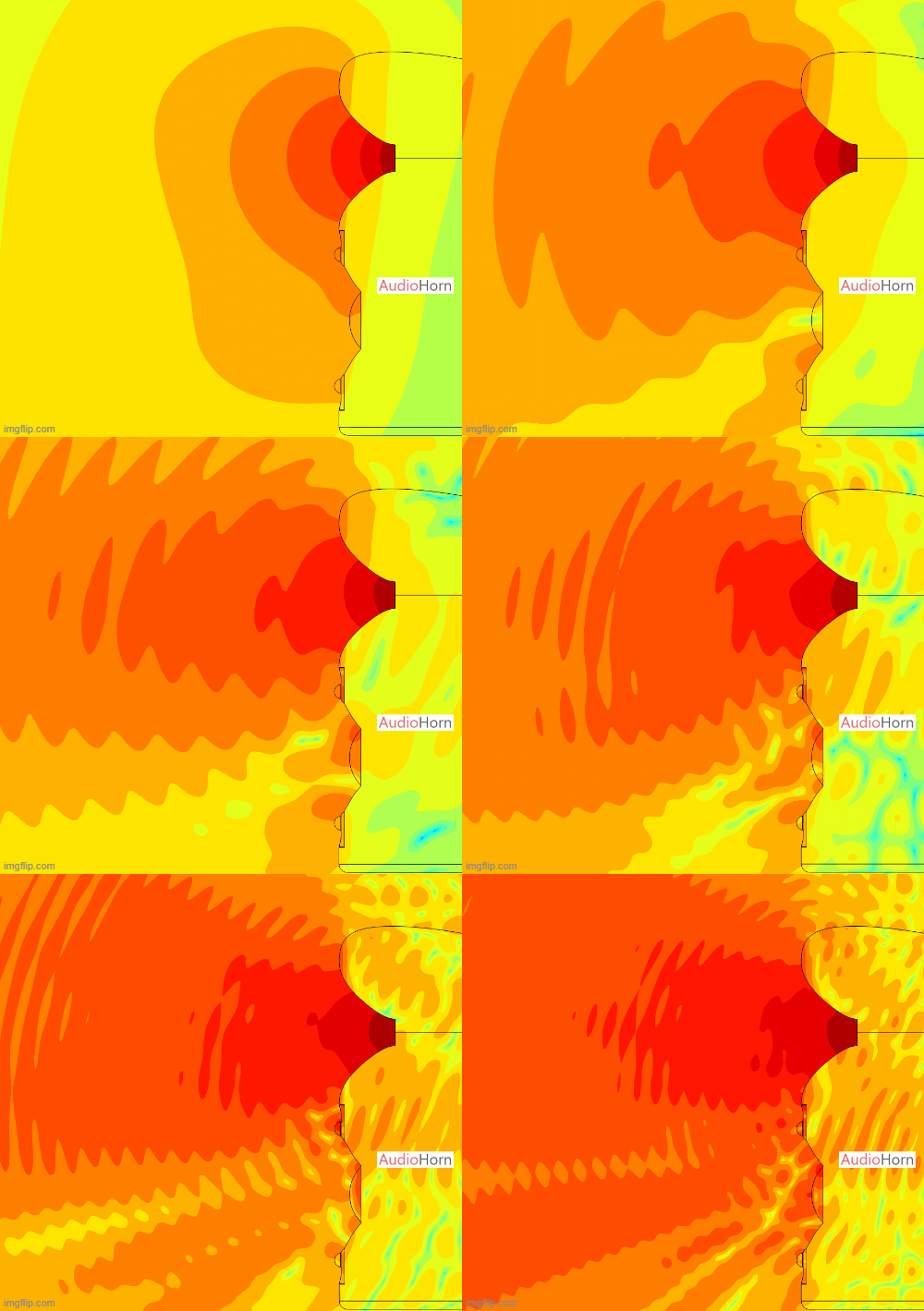
We can observe the impact of diffraction on the woofer’s shape.
The closer the woofer is to the high frequency device, the more pronounced the diffraction, especially if the implementation is not perfect or if the woofer surround is very prominent. This phenomenon has an impact on the vertical polar plot.
From the woofer’s perspective, the wavefront continues inside the horn, creating a kind of virtual or phantom source, we can observe it here from 200 to 2000 Hz:
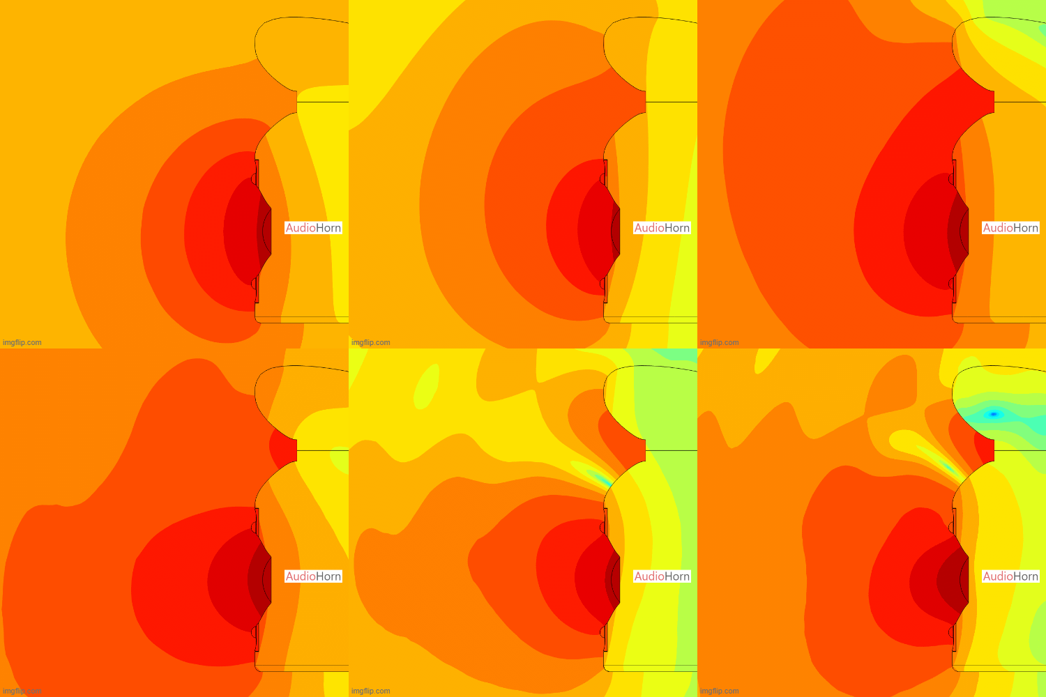
This also explains why the horn tends to be the overall virtual point source of emission for the entire speaker, while in a regular speaker, it’s between the tweeter (in direct radiation) and the mid-woofer.
These diffractions significantly affect the vertical polar response and even the horizontal one when components are very close. This diffraction, present in all speaker designs, becomes more problematic when a waveguide is added to the mid-woofer and the vertical center-to-center spacing is less than 17-20 cm.
Worst Case: Adding a Square Waveguide to the Mid-Woofer
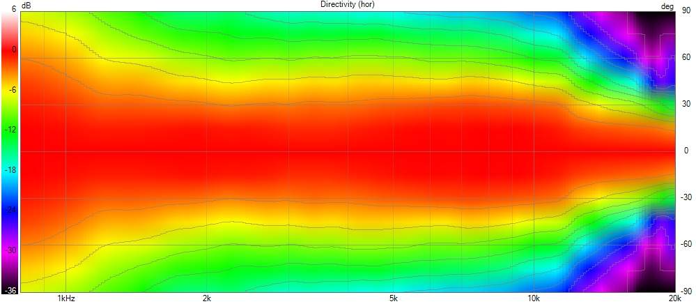
Here are two polar plots of a tweeter waveguide, one with the horn alone and another with a mid-woofer also using a waveguide at a center to center distance of 15 cm, but with the mid-woofer not emitting sound.
- Horizontally:
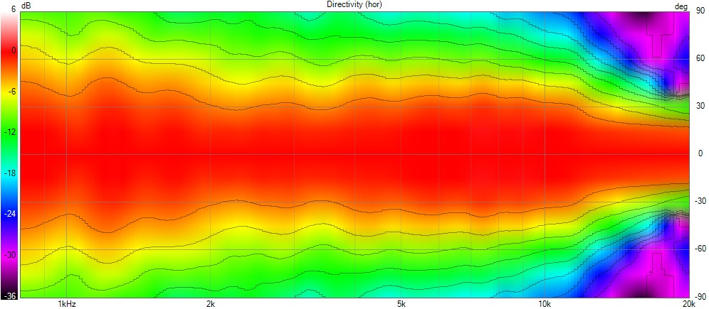
- Vertically:
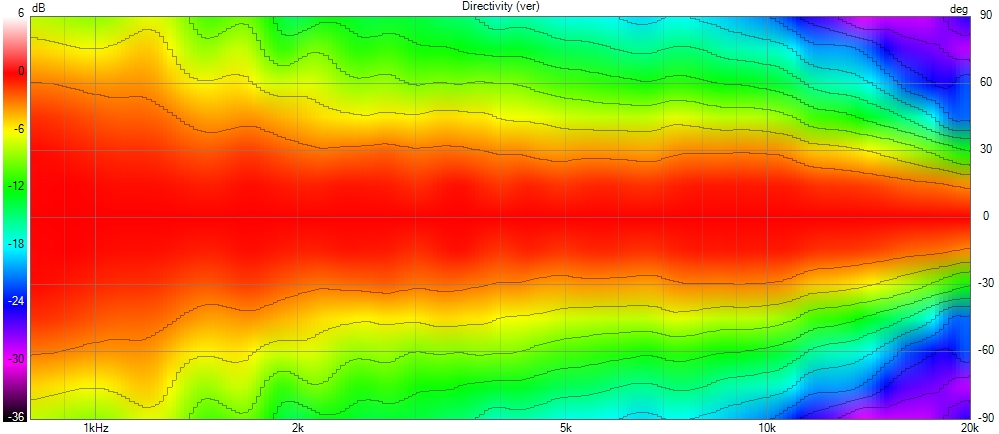
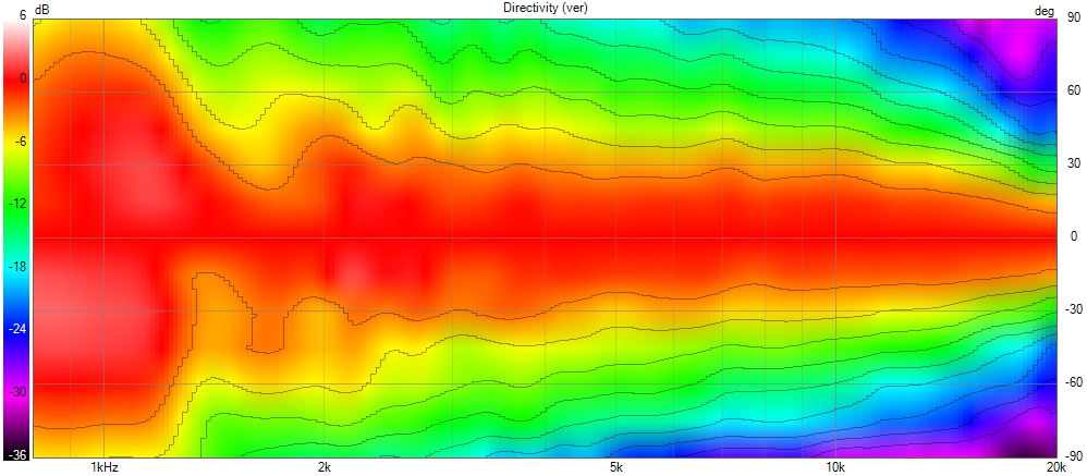
Therefore, when the vertical center-to-center spacing between two components is less than 17–20 cm, the problem is worsened as in our current example. Adding a waveguide to the mid-woofer in this situation should be avoided.
An MTM arrangement will also exacerbate the problem.
Why it becomes less impacting when vertical center to center increase ?
By increasing the distance, you slowly move the impacted frequency range downwards so the impacted wavelength becomes larger, the impacted energy level also decreases slightly. But this frequency range will remain wide.
To increase the distance without introducing lobe problems, you will need to lower the crossover frequency so to use a larger horn so a bigger mid-woofer too.
Increasing vertical spacing allows longer wavelengths to pass through, reducing the obstacle’s (woofer surround or woofer shape) impact. Consequently, the obstacle appears less significant from the perspective of these longer wavelengths.
Technically: By increasing vertical spacing, the obstacle becomes less effective at obstructing longer wavelengths. This reduces the obstacle’s apparent size or “visibility” to these wavelengths.
We can argue that if we increase the distance and lower the crossover frequency, the woofer, as well as the horn, will be bigger. Consequently, the woofer’s surround will also be larger. Even if the impacted wavelength is larger, the woofer’s surround will still be a visible obstacle due to its increased size.
However, the wavelength will increase faster than the woofer surround size, ultimately reducing the woofer’s surround diffraction impact by increasing the vertical distance with the high frequency component. Of course, it will requires larger components and a lower crossover frequency.
Coaxial or MEH Diffraction
Diffraction also applies to coaxial or MEH. It can even be worse, as the obstacle – for example, the coaxial surround – is completely symmetrical around the center of emission.
This concentrates the problem and makes it even more pronounced if the surround and/or any other possible obstacles are not smoothed. These concentrated artifacts further affect a directivity that is already less uniform and clean than that of a well-implemented constant directivity horn.
The polar responses of these systems can be seen in the MEH and coax sections of our MTM, 2.5 or 3 voices article.
Standing Waves
In contrast to diffraction, standing waves occur when a wave reflects off a boundary and interferes with itself.
The reflected wave can either add up (constructive interference) or cancel out (destructive interference) with the incoming wave, creating specific points of vibration and stillness.
Standing waves are less relevant within the horn itself if the horn has a smooth profile, but they can appear at the horn mouth, contributing to midrange beaming when the termination is abrupt or non-smooth.
These standing waves can cause midrange beaming, our Mid-range Beaming And Narrowing article goes deep in these two concepts.
Understanding Wave Behavior: Diffraction vs. Standing Waves
It’s important to clarify that diffraction doesn’t actually break the wavefront into separate pieces. Instead, the wavefront itself bends and spreads as it encounters obstacles or openings.
In contrast, standing waves arise when reflections occur at abrupt edges or non-smooth terminations, creating waves that interfere with the original wavefront. The reflected wave can superimpose on the original, creating regions where the peaks (crests) and troughs (valleys) reinforce each other (constructive interference) or cancel each other out (destructive interference). These regions of reinforcement and cancellation create a stationary pattern of vibration, hence the term “standing wave.” The wavefront itself, however, remains intact.
Coloration and Wave Interactions
Diffraction and standing waves, while interesting phenomena, can introduce unwanted colorations to the sound. These wave interactions can emphasize or weaken certain frequencies, leading to an uneven and distorted representation of the original sound.
For instance, diffraction around obstacles or improper horn design can bend the wavefront around obstacles, sometimes even partially destroying it, leading to frequency-dependent dips and uneven high-frequency response.
Similarly, standing waves can introduce peaks and nulls in the listening area, boosting or canceling specific frequencies.
These effects can manifest as a thin or bright sound lacking body, or an overly harsh and emphasized high-frequency range.
By understanding these wave interactions, we can design audio systems that minimize coloration for a more accurate sound reproduction.