Cross wavefront syndrome: Diagonal matter
Wavefront Basics and Challenges:
Sound travels in waves, and the shape of the wavefront determines how the sound propagates in horns. Ideally, the wavefront should smoothly follow the horn’s curvature for optimal constant directivity (controlled sound dispersion).
However, horns with diagonal sections pose a challenge. A wavefront, while traveling at the speed of sound, inherently wants to maintain a 90-degree angle to its edges.
This tendency is crucial when the wavefront encounters sudden geometry changes, like those found in diagonal horn sections.
These rapid transitions can “pull” and deform the wavefront in some points, causing a phenomenon called diffraction (bending and spread out).
The Problem: Cross Syndrome in Horns or Waveguides
When a round waveguide transitions too quickly to a square or rectangular shape, bypassing the elliptical stage or another smooth way to do, it creates a sudden change in the wavefront’s edges expansion rate.
This rapid change causes diffraction primarily at the diagonals, disrupting the wavefront in high frequencies. This phenomenon can be named “cross syndrome” as the wavefront will form a cross shape.
Why We Hear It: Audibility
Even subtle changes in the direct sound caused by diffraction will be audible due to how we listen in rooms.
Most listening happens within the “critical distance” where both direct sound from the speaker and reflected sound bouncing off walls contribute significantly in a ratio close to 50/50.
This means even diffraction effects off axis become noticeable even when listening directly in front of the speakers.
These compromised wavefront are audible and present in your listening experience. This will lead to a:
-
“Floating” sensation: The compromised wavefront might seem disconnected from the rest of the soundstage, creating an unnatural spatial impression.
-
Shifting power response: As the off-axis sound degrades with increasing frequency due to diffraction, the perceived balance of the sound can change, making it seem less powerful or detailed at higher frequencies.

A proper wavefront should be round or elliptical, not cross shaped. The horn mouth is not in cause, it’s the overall profile.
Why some measurement don’t detect it
A horizontal polar is done at a 0° vertical position, and a vertical polar is done at a 0° horizontal position. This means that the measurement is valid on two 2D planes.
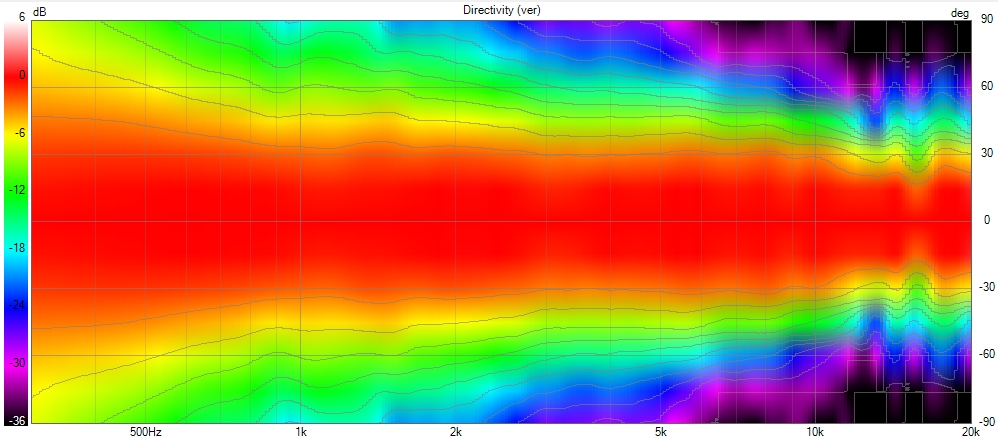
Some designs that can suffer from cross wavefront syndrome, such as MEH/synergy horns, should be measured diagonally, and a diagonal polar plot should be provided.
We also need to pay attention to scale. A “half-space” option in VituixCAD displays the polar response over 180° instead of 360°. If we stay in the 360° mode, the scale is affected, and the polar response may appear more consistent than it actually is.
The same issue exists with the color scale, where using solid colors for a 2 or 3 dB range instead of a gradient can hide certain problems.
Lastly, an even simpler issue is with polar maps that start at 0 dB or use the same color for ranges like +6 dB to -2 or -3 dB (and sometimes even down to -6 dB). This completely obscures the true response of the horn.
AudioHorn Solution
X-Shape horns and PureShape tweeter waveguide address this problem by focusing on the diagonal transitions.
Using advanced Finite Element Analysis (FEA), a specific diagonal profile is designed to ensure the wavefront maintains its integrity, even along these critical axes.
This allows the wavefront to smoothly follow the curvature without encountering drastic changes in geometry, removing diffraction as we can see here with a polar of the X-Shape diagonal (the worst place to measure a horn) :
