Horn Loading
Horn Loading and Efficiency
Horn loading is a technique used in loudspeakers to improve efficiency by shaping how sound is transferred from the driver to the surrounding air. This article explores the different aspects of horn loading, its frequency dependence, and its relationship with directivity and wavefront geometry.
We will expose technical considerations necessary for a full understanding of the phenomenon, then present a conclusion.
Acoustic Impedance
Acoustic impedance (Z) is defined as the ratio of sound pressure (Pa) to particle velocity (v):
Z = Pa/v
It characterizes how easily an acoustic wave propagates through a medium or across a boundary between two media. In practice, acoustic impedance measures the adaptation between two acoustic environments, such as a loudspeaker coupling into a room, or a compression driver coupling into a horn.
Acoustic impedance is not directly audible. Instead, it governs how much of the acoustic energy is transmitted versus reflected at a boundary. A well-matched acoustic impedance maximizes energy transfer and minimizes unwanted reflections.
In horn-loaded loudspeakers:
- At low frequencies, where the wavelength is larger than the horn dimensions, the horn does not load efficiently and the acoustic impedance mismatch leads to reduced efficiency.
- At mid frequencies, the horn improves the impedance match, thereby boosting efficiency.
- At high frequencies, the impedance tends to rise again due to smaller wavelengths and internal viscous losses, reducing the overall gain.
Additionally, directivity impacts impedance: as a source becomes more directional (naturally or by design), the radiated impedance increases. Horns use this effect intentionally to “concentrate” the energy, but it must be controlled to avoid creating too much mismatch at the horn mouth.
Finally, acoustic impedance at the horn throat typically increases with frequency, and a very high impedance combined with high particle velocity can lead to thermal compression and distortion at high SPL levels.
With a horn featuring a smooth roundover at the mouth to avoid midrange narrowing, the acoustic impedance at the horn’s mouth approaches that of free air—very low and nearly linear—while the horn geometry progressively transforms this impedance towards the throat, ensuring efficient coupling with the driver.
Acoustic impedance is a complex quantity, comprising both resistive (dissipative) and reactive (energy-storing) components.
The horn influences both parts, but the reactive load is especially important as it temporarily stores and releases acoustic energy, shaping the frequency response and directivity of the system.
Reactive Loading
Reactive loading refers to the non-dissipative component of acoustic impedance — the portion that stores, rather than dissipates, energy.
In an acoustic system such as a horn, certain elements — like the confined volume of air near the throat — behave somewhat like a spring or a mass, temporarily storing energy in the form of potential or kinetic energy without dissipating it.
This reactive impedance resists rapid changes in pressure or displacement and varies with frequency.
At low frequencies, the confined air acts as an acoustic compliance (spring), increasing the total acoustic impedance and improving energy transfer from the driver to the air.
At high frequencies, this effect decreases, as the wavelength becomes shorter and the confined air no longer behaves as a significant reactive load.
In short, reactive loading is the frequency-dependent acoustic impedance caused by the storage of elastic energy in the air near the throat (and other regions), which helps match the transducer to free air — especially at low frequencies.
Particle Velocity
Particle velocity (v) is the oscillating motion of air particles caused by a sound wave. It differs from the speed of sound (celerity), as it describes the back-and-forth movement without any net displacement.
In audio systems:
- High particle velocity typically occurs in constricted areas, such as bass reflex ports, narrow ducts, or horn throats.
- At constant sound pressure, higher particle velocity means lower impedance.
- In general, as the cross-section narrows, the particle velocity rises, even if the frequency or SPL remains constant.
Thus, particle velocity must be carefully monitored when designing small apertures or highly compressed structures to avoid excessive velocities that cause distortion and energy losses; controlling it properly helps minimize nonlinear distortion and maximize power handling.
These nonlinear effects extend beyond simple harmonic distortion — they also generate intermodulation distortion, which arises from the interaction of multiple frequencies. Intermodulation distortion particularly degrades clarity and precision, adversely affecting the perceived fidelity of the sound.
The particle velocity within the throat limits the maximum power the horn can handle. This is why compression horns often feature throats with an optimized diameter — to control particle velocity, reduce turbulence and flow losses due to viscous and thermal boundary layer effects at the throat walls, and prevent the flow from exceeding the critical Mach threshold.
However, modern phase plugs allow for much higher compression ratios by ensuring equal impedance across each acoustic path.
This design distributes particle velocity more evenly, reducing local velocity peaks and enabling greater power handling without increased distortion, or allowing a smaller throat size to extend directivity control to higher frequencies without sacrificing maximum power.
Critical Mach Number
The critical Mach number describes when the particle velocity becomes a significant fraction of the speed of sound (Mach 1). In loudspeaker design, this is particularly relevant in narrow passages or throats where particle velocity can increase substantially.
The Mach number is defined as:
M = v/c
Where:
- v is the particle velocity,
- c is the speed of sound in the medium (≈ 343 m/s in air).
At a Mach number of around 0.1 to 0.3, the acoustic behavior starts to become nonlinear. Exceeding this critical Mach number results in:
- Strong nonlinearities (distortion),
- Turbulent flow,
- Thermal compression (heating due to intense localized motion),
- Potential efficiency loss and audible degradation.
Keeping particle velocity well below the critical Mach number ensures low distortion and optimal efficiency in horn-loaded designs.
For ports, we have developed a flat velocity port that allows us to keep the Mach number low.
How These Concepts Interact with Frequency
The interaction between reactive loading, acoustic impedance, particle velocity, and the Mach number depends strongly on frequency.
-
At lower frequencies, reactive loading dominates. The confined air near the horn throat acts as an acoustic compliance, temporarily storing energy and improving energy transfer from the driver to the air. Sound waves have longer wavelengths, which results in lower particle velocities, reducing the risk of reaching the critical Mach number. Horn-loaded systems generally handle these frequencies efficiently, with minimal distortion or turbulence, benefiting from the positive effect of reactive loading.
-
At higher frequencies, wavelengths become shorter and particle velocity increases more rapidly. In narrow openings, such as the throat of a horn or the port of a bass reflex system, the risk of exceeding the critical Mach number rises. This can cause distortion, thermal compression, and reduced efficiency.
In practice, these effects occur mainly at very high SPLs or with extremely narrow throats. Modern phase plugs and impedance-optimized designs help manage airflow, reducing peak particle velocities and mitigating nonlinearities, while still allowing efficient sound radiation.
Proper impedance matching remains essential in horn design to minimize reflections and ensure optimal energy transfer. At higher frequencies, impedance tends to increase at the throat due to viscous and thermal losses, which can partially offset the efficiency gains from the horn.
In summary, frequency, horn geometry, throat size, and intended SPL all contribute to the balance between reactive loading, particle velocity, Mach number, and impedance. Understanding these interactions is key to achieving optimal performance across the horn’s operating range.
High-Order Modes (HOMs) in Horns
High-Order Modes (HOMs) are unwanted sound waves that can occur within a horn due to its geometry.
They deviate from the ideal plane wave propagation, causing peaks and dips in the frequency response as well as localized internal resonances.
These resonances affect directivity and linearity, coloring the sound and compromising acoustic neutrality and transparency.
Minimizing HOM Excitation
A well-designed horn aims to:
- Maintain a flat impedance profile across the desired frequency range. This helps to suppress the excitation of HOMs.
- Have a smoothly expanding horn throat to encourage the propagation of the fundamental wave mode (desired sound wave) and discourage the excitation of higher-order modes.
Influence of Throat Geometry and Mass Corner on Horn Loading
The way a horn loads the driver is primarily dictated by the throat design and the expansion profile, but the mass corner of the diaphragm also plays an important role.
-
Throat geometry and expansion: A longer, more constricted throat increases low-frequency loading by enhancing impedance matching at low frequencies. However, this comes at the cost of increased acoustic resistance at higher frequencies, which can reduce efficiency and bandwidth in the upper midrange and treble. Conversely, a rapid flare (wider throat expansion) improves high-frequency performance but sacrifices low-frequency loading because of poorer impedance matching.
-
Mass corner effect: The mass corner defines the transition between compliance-controlled (spring-like) and mass-controlled (inertia-like) behavior of the diaphragm. Above the mass corner, the diaphragm operates in a mass-controlled region where energy transfer into the horn is more efficient. Below the mass corner, the diaphragm becomes increasingly compliance-controlled, making efficient horn loading more difficult.
Thus, horn loading performance results from a combination of throat geometry and diaphragm behavior relative to its mass corner. When experimenting with different throat characteristics, a horn may appear to shift its frequency response at a certain point. This isn’t solely due to the mass corner or the horn’s geometry—it’s the result of both.
In classic direct-radiating loudspeakers with horn-loaded cones, it’s possible to optimize the impedance match between the cone and the horn’s throat by carefully designing the throat profile, like with a compression driver, thus minimizing efficiency loss around the mass-controlled transition while maintaining good loading.
Impedance Matching and Low-Frequency Considerations
For a cone driver in a horn-loaded speaker, impedance matching between the diaphragm and the throat is crucial, especially at higher frequencies, as this helps maximize SPL and minimizes energy losses due to reflections.
However, as frequency decreases toward lower midrange and bass regions, impedance matching becomes less critical for the following reasons:
-
Longer wavelengths allow the throat to behave more “linearly” at lower frequencies.
-
Acoustic resistance of the throat becomes less significant at lower frequencies, as pressure variations are smoother and energy propagates better over longer wavelengths.
-
The horn’s low-frequency loading effect becomes more dominant, and impedance matching has less impact.
In summary:
-
At high frequencies, proper impedance matching between the diaphragm and the throat is crucial for efficient energy transfer, minimizing reflections, and maintaining consistent frequency response.
-
At low frequencies, imperfect impedance matching has a reduced impact on efficiency. Horn design at these frequencies is more concerned with maximizing acoustic loading and maintaining extension, rather than achieving a perfect impedance match.
How a Horn Increases Efficiency at Low Frequencies
The loading of a horn depends on several factors, including:
-
Horn Geometry: The geometry of the horn, particularly the throat design and the expansion profile, strongly affects the acoustic loading and impedance matching. Surface propagation and horn depth also play a role, but the throat shape and expansion law are the primary factors.
-
Mouth Size and Directivity Control: The size of the horn mouth largely defines where directivity control ends, particularly in the horizontal plane. If the horn loses control in the vertical plane too early, a portion of the acoustic energy can be lost or dispersed unpredictably, leading to reduced efficiency.
-
Frequency of the Sound: Frequency fundamentally influences how the horn interacts with air impedance and controls sound radiation. Lower frequencies require larger horns to maintain good loading and directivity.
Here’s a breakdown of the key points:
-
Acoustic Loading: A horn acts as an acoustic transformer, influencing the acoustic impedance “seen” by the compression driver. This allows for a better match between the driver’s impedance and the horn’s impedance profile across the desired frequency range, improving efficiency and sound radiation characteristics.
-
Low Frequency Efficiency: At low frequencies, the impedance mismatch between the driver diaphragm (high impedance) and the air (low impedance) hinders efficient energy transfer.
-
Matching the Air Load for Efficiency: Air has a relatively low acoustic impedance compared to the diaphragm of a compression driver. This impedance mismatch can lead to inefficient energy transfer from the driver to the air. A well-designed horn can influence the impedance profile “seen” by the driver, particularly at low frequencies. This allows for a better match between the driver’s impedance and the radiating medium (air). This improved impedance match can lead to increased efficiency, allowing the driver to operate with potentially reduced diaphragm movement for the same sound output (dB).
-
Reduced Diaphragm Movement: With improved impedance matching, the driver needs to move less to produce the same sound pressure level at low frequencies. This reduces distortion and improves the overall efficiency of the driver.
Important Note:
This principle primarily applies to low frequencies. At higher frequencies, the horn’s effect on impedance matching becomes less significant, and other factors like diaphragm size and material come into play.
The “loading effect” is frequency-dependent. It has a stronger influence at lower frequencies and gradually diminishes as frequency increases.
For more information on energy distribution in horns, see : Horn and energy
A point about Constant Directivity Horns:
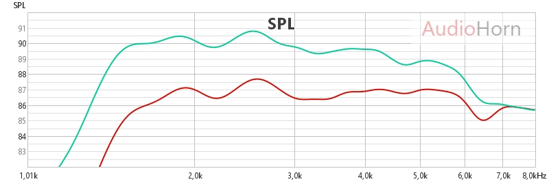
Since energy isn’t “free,” a constant directivity horn redistributes some of it off-axis to maintain consistent coverage. As a result, the on-axis response often shows a dip or a broad bell-shaped curve.
Conclusion
Importance of Throat
Building on the concepts developed in this article, it becomes clear that a deeper horn — meaning one with a longer throat before the flare — significantly improves acoustic loading in the lower portion of its usable bandwidth.
At higher frequencies, where wavelengths are shorter, this reactive loading (i.e., frequency-dependent impedance due to stored acoustic energy, like air mass or compliance near the throat) diminishes, reducing the acoustic impedance and therefore the loading effect.
At low frequencies, horn efficiency is largely driven by the acoustic loading effect at the throat. This occurs because, at these frequencies, the acoustic wavelength is large compared to the throat dimensions, causing the confined air near the throat to behave as a reactive element — primarily as acoustic compliance and inertance — which increases the acoustic impedance seen by the driver.
This impedance rise at low frequencies enhances energy transfer by better matching the high impedance of the transducer diaphragm to the very low impedance of open air — a transformer effect provided by the horn.
A deeper and properly proportioned throat allows for a more gradual impedance transition, enabling more acoustic energy to be transmitted with less diaphragm excursion. This leads to higher sound pressure levels for the same excursion, reduced reflection losses, and lower particle velocity at the mouth — which limits distortion risks and prevents exceeding the critical Mach number.
This efficiency gain is especially noticeable in the lower range of the horn’s operating bandwidth, where wavelengths are long and direct radiation would be very inefficient without a guiding structure. Horns designed for low-frequency extension often feature a narrow, long, and well-profiled throat. This geometry promotes more stable loading, better efficiency, and reduced distortion.
However, a too long or too narrow throat can cause viscothermal losses, encourage higher-order modes (HOM), generate unwanted transmission line resonances, or increase acoustic resistance and distortion at high frequencies, ultimately degrading the horn’s overall performance. These phenomena, collectively known as “Honk”, primarily degrade efficiency and linearity in the upper frequency range. Therefore, this part of the horn must be carefully designed to balance effective acoustic transition with control of these secondary effects.
Loading and Directivity
Reactive loading is important because it allows the horn’s directivity control band, which remains fixed, to be more effectively filled, while the reactive load itself can be positioned at a specific point within this band. As long as this directivity control is maintained, the energy stored in the reactive load is efficiently transferred into the horn’s radiation and focused along the intended axis. When control is lost, this becomes more noticeable, since energy remains strongly present just above the cutoff frequency, enhancing the perceptual transition.
In other words, horns with a more gradual low-frequency slope are less reactively loaded, whereas horns with higher reactive loading exhibit a sharper fall at the end of the band. This abrupt cutoff provides an appreciable “free” SPL gain just before the limit of control, making these horns particularly effective in extending low-frequency response.
Reactive loading is frequency-dependent, decreasing as frequency increases. This explains why high-frequency points — such as the “anchor point” around 14–15 kHz used for our horn EQ — remain largely unaffected by loading, while still depending on the horn’s directivity behavior.
Another important factor is off-axis energy distribution: at a given frequency, energy radiated off-axis is no longer present on-axis. This is one reason why pursuing constant directivity up to 20 kHz is not necessary, especially when considering audibility thresholds and psychoacoustics.
Non-Uniformity of Loading
It is also critical to understand that loading is not uniform. The combination of expansion geometry and surface area creates a pressure curve over frequency, which interacts with the energy distribution imposed by directivity. This complex interaction defines the range and effectiveness of acoustic loading in conjunction with the driver’s output.
![]()