Horn Response, Hiss and Equalization
Horn Response
When looking at a horn’s frequency response, a dip in high frequencies compared to mid frequencies might lead you to believe you’ve “lost” decibels (dB) and need to boost the highs with additional amplification.
However, this way of thinking is not accurate and we will see here why.
To gain a more comprehensive understanding of the concepts discussed here, particularly about horn loading (energy) and constant directivity, we recommend referring to our articles dedicated to these subjects.
Essentially, the bell response of a horn arises from the combined influence of its directivity pattern and acoustic loading effect. While constant directivity horns typically maintain a consistent directivity behavior up to around 7-8 kHz, the acoustic loading effect is inversely proportional to frequency. This means it has minimal impact on high frequencies.
Bell Response and Energy Balance
The interplay between driver characteristics, horn loading and horn directivity creates a phenomenon known as the “bell response”.
This describes a perceived roll-off in high frequencies. However, it’s important to understand that this doesn’t necessarily mean there’s less high-frequency energy overall.
The reasons of the bell response are:
Larger diaphragm compression drivers produce more low-midrange energy compared to smaller ones. So in comparaison the high frequency can look lower than a tinier diaphragm when in fact that is mainly the medium range that is upper.
The horn’s loading effect enhances this low-midrange presence, that is a very important aspect, as the loadding effect is strongly inversely proportional to the frequency, more we goes up in frequency less we have it. So for two horns that are constant at the same frequency, reducing coverage (see the point below) will principaly gives more SPL in low end.
Directivity distribution of the initial energy as we have seen upper, this initial energy will always remains the same, it’s the way to distribute it that change and affect the on-axis response.
This can make the high frequencies seem less prominent in comparison to medium, creating the bell response.
When we see these high frequency lower than medium in comparison we tend to thinks that we have “lost” dB in high frequency, we will see that in fact it doesn’t work like this in Horn Response and Hiss article,
In most cases we in fact have “gain” in the midrange area, it’s the high frequency level that doesn’t have moved.
Flattening Frequency Response with EQ
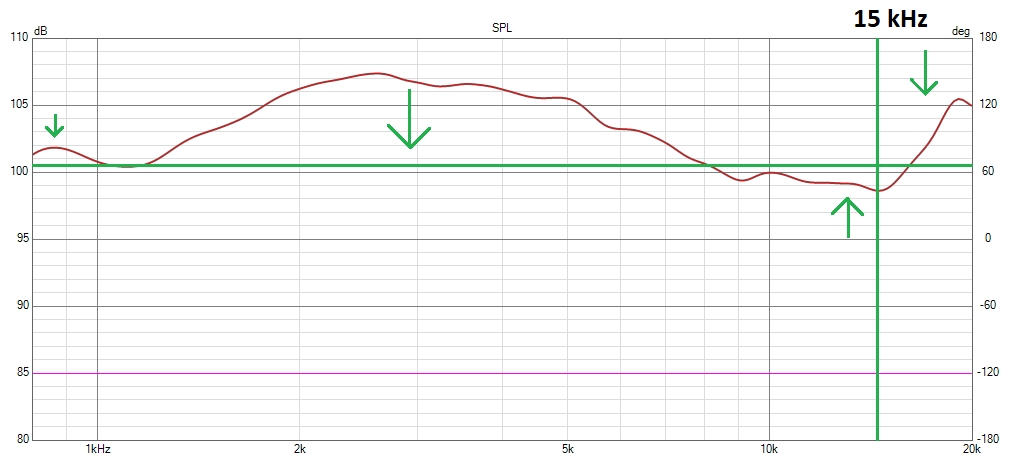
Typically, to achieve a flat on-axis frequency response, we choose a reference frequency above which we want a flat response. This is often set at 15 kHz.
Beyond this point, we allow the natural roll-off of the driver to occur, or use equalization (EQ) again if there’s a rise.
Negative or positive EQ can be used to achieve a flat response. The direction (positive or negative) isn’t crucial, the final result will be the same.
The primary goal is to avoid clipping (in the source, DSP, or amplifier) and maintain a proper gain structure to our desired maximum power output.
Minimum-phase EQ (IIR) is a valuable tool for correcting on-axis horn response because it addresses both the frequency response and the phase response simultaneously.
When a significant dip or peak occurs at a specific frequency, minimum-phase EQ (IIR) not only corrects the level at that frequency but also adjusts the phase response in a way that complements the level correction. This combined effect helps to achieve a more linear overall frequency and phase response.
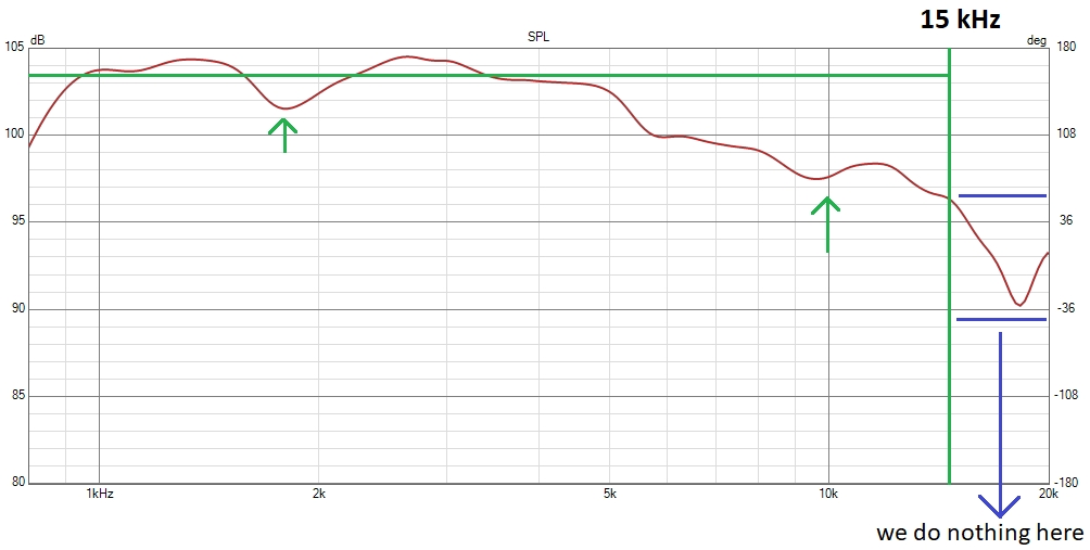
Here are two EQ examples for an X-Shape X25 horn
BMS 5530 one:

18Sound 1095N one:

Our article about audibility can help to understand one of the reasons why we do nothing after 15 kHz in the 1095N case.
This region is also where the breakup occurs, that is the second main reason why we don’t try to increase volume here.
In each case 15 kHz is our anchor point, EQ are different but the main judge will be, as alway, the distortion after having EQ it flat below 15 kHz, as we have seen on our 1" compression driver test.
If we push constant directivity very high on the same horn, way after 7/8 kHz, the effective loss of energy in 12/17khz area will be in fact minimal, around 1 or 2dB maximum.
Its due to the fact that only directivity will impact it and not the loading effect.
L-PAD
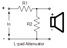
To reduce hiss and protect the driver, an L-pad to reduce driver sensitivity is often recommended; it’s a simple resistor network placed just before the driver:

You can simulate appropriate L-pad values using VituixCad, considering the driver’s impedance and the horn on-axis response. For the X25 horn, this might involve a 1.5-ohm resistor in parallel and a 12-ohm resistor in series, depending on the desired dB reduction to match the mid-woofer level.
The L-pad resistor network does not degrade audio quality; it simply absorbs some amplifier energy which therefore does not reach the compression driver or tweeter.
S/N ratio and Hiss
Hiss is a low-level noise often noticeable in high-sensitivity components related to the system’s signal-to-noise (S/N) ratio.
A common concern when comparing horns, especially regarding EQ use, is increased hiss.
It might seem that extensive EQ adjustments, along with the gain changes needed to achieve a flat response,
would increase hiss, reduce S/N ratio, or consume more power.
However, this vision is partial. Here’s why:
-
Power Amplifier: No change in S/N ratio or hiss.
-
Our reference frequency is 15 kHz. Constant Directivity Horns stop exhibiting constant directivity behavior around 7-8 kHz.
-
Therefore, directivity above this point has minimal impact on energy at 15 kHz, which is mostly dictated by the driver.
-
Acoustic loading is inversely proportional to frequency and has almost no influence at 15 kHz.
-
-
DSP: Slight decrease in S/N ratio.
- Extensive EQ adjustments may slightly increase noise as they consume part of the DSP’s dynamic range, but systems typically operate well below their maximum range (around 96-125 dB), so this effect remains minimal.
In conclusion, while EQ adjustments might influence how the DSP perceives the S/N ratio, the impact on hiss is still minimal.
Conclusion
For a given driver, the energy level at 15 kHz is mainly determined by the driver itself, regardless of horn type or coverage area.
Different constant directivity horns generally have similar hiss levels and S/N ratios when using the same driver.
The bell response is not a problem but relates to both directivity and loading effects:
-
It shows the horn is constant directivity; a flatter response may indicate a narrower coverage horn.
-
The loading effect in mid and low frequencies provides an energy “bonus” that reduces overall distortion and allows lower crossover frequencies.
-
EQ adjustments may influence how the DSP perceives the S/N ratio, but impact on hiss is minimal.
-
From the amplifier’s perspective, there’s no change in S/N ratio. Even pushing constant directivity beyond limits reduces it only by 1-2 dB.
-
The L-pad allows for adjusting overall sensitivity and counteracts the amplifier’s inherent noise.
-
Advanced users can use passive equalization (RC networks) to limit EQ application and preserve DSP dynamic range.
-
Effects also depend on compression driver characteristics.