Mid-range beaming and narrowing
The Challenge of Midrange Response
In loudspeaker design, achieving a smooth and balanced frequency response across the entire spectrum is a continuous pursuit. One specific challenge lies in the midrange frequencies (typically around 1 kHz).
Here, two unwanted phenomena can significantly impact the sound and his power response: midrange narrowing and beaming.
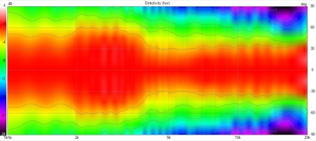
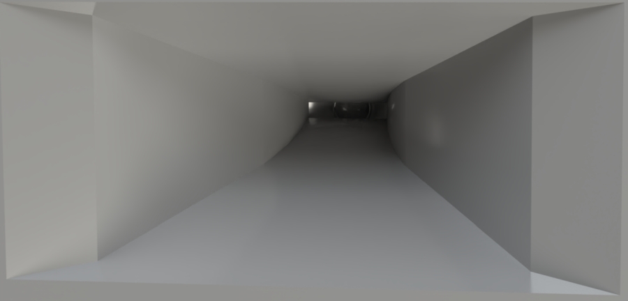
Here we can see a not fully optimised end of profile resulting a narrowed mid-range in 1kHz region :
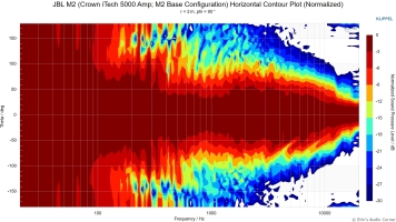
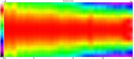
Whatever the horn, wageguide, integrated on baffle or not, the contour must be fluid in all directions.
Midrange Narrowing: A Dip Caused by Diffraction
Midrange narrowing refers to a decrease in sound pressure at specific midrange frequencies, mainly off-axis.
This occurs due to edge diffraction. As sound waves radiate from the driver and encounter the sharp edges of the speaker baffle or horn mouth, they attempt to follow the surface. The edges of the wavefront naturally strive to remain perpendicular (≈90°) to the surface they touch.
However, abrupt changes in the profile (like a sharp edge) force the wavefront to bend excessively. This “over-diffraction” leads to a premature wavefront peeling, causing the wave to detach from the surface and narrow its radiation prematurely. This detachment interferes with the direct wavefront, creating the characteristic dips observed in the midrange response, affecting both on-axis and off-axis radiation.
Midrange Beaming (Lobing): Off-Axis Irregularities Due to Secondary Radiation
While midrange narrowing describes the initial narrowing of the beam, further edge diffraction effects lead to midrange lobing.
This phenomenon arises when the wavefront hits the cabinet edges, creating secondary radiations (acting like “phantom” sources) that interfere with the main wavefront. Because these diffracted waves are delayed and often out-of-phase, they alter the sound pressure differently depending on the angle.
The resulting interference patterns produce constructive interference at certain angles, creating peaks, and destructive interference at others, leading to dips. This creates an uneven radiation pattern where energy is no longer distributed smoothly, but is instead concentrated or cancelled in specific lobes. This phenomenon compromises the overall soundstage and negatively affects the listening experience across the room.
The Impact on Listening Experience
The combined effects of midrange narrowing and beaming can significantly alter the way we perceive sound. Here’s how:
-
Reduced Clarity: The dip in the midrange response, even on-axis, can weaken the presence of vocals, instruments playing in this frequency range (guitars, pianos), and essential details in the overall sound.
-
Uneven Tonality: The variations in sound pressure across the entire response (on and off-axis) can lead to an unbalanced listening experience, where the sound might appear brighter or duller depending on the listener’s position relative to the speaker.
-
Narrowed Soundstage: The uneven off-axis response can restrict the perceived width and depth of the soundstage, making the sound seem less immersive for listeners positioned off-axis.
-
Compromised Power Response: The ideal combination of direct sound from the speaker and reflected sound from the room (reverberant field) at the critical distance (the distance where these two components are roughly equal) is crucial for a natural listening experience. Midrange narrowing and beaming can disrupt this balance, affecting the perceived loudness and fullness of the sound.
Optimizing Baffle Design for Smooth Midrange
To address these challenges and achieve a smooth midrange response, loudspeaker designers employ various strategies:
-
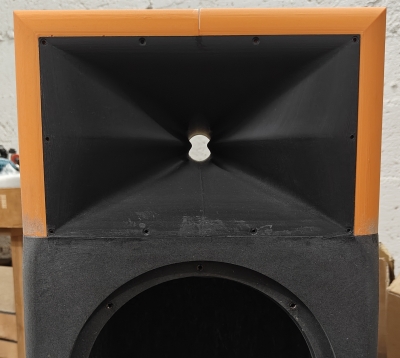
Round-Over Returns and Sharp Edges removing: A smooth, curved transition where the horn profile meets the baffle minimizes disruptions to the wavefront, reducing both midrange narrowing and beaming. Finding the ideal radius for the round-over depends on the specific horn profile. It requires balancing diffraction reduction with practicality.
-
Fluid Profile Integration: Seamless integration of the horn with the baffle is crucial. The combined profile should be continuous and avoid abrupt transitions on both the front and side of the baffle, minimizing opportunities for edge diffraction.
-
Horn and Baffle as One: Ideally, the design strives for the horn and baffle to function as a single unit with a continuous profile. This ensures optimal wavefront propagation and minimizes diffraction effects.
For flat baffles, a simple round-over return might not be sufficient. In those cases, designers may employ profile acceleration and deceleration, this involves a gradual transition from the horn’s curvature to the flat surface of the baffle, minimizing the impact of abrupt changes on the wavefro
Advanced Design Techniques
Modern loudspeaker design tools like Finite Element Analysis (FEA) simulations allow for precise modeling of baffle shapes and their impact on sound radiation. This facilitates the optimization of baffle profiles to minimize diffraction effects and achieve a smooth, balanced midrange response.
Exception: Low midrange horns
Low midrange horns, typically wide horns (around 1 meter) used between 800 and 250 Hz, are a special case:
-
They are used in the bottom of their control range where midrange narrowing is present and the wavelength is long. The top range of this kind of horn is not typically used as it would significantly shift the acoustic center relative to the crossover wavelength.
-
We need to achieve as much low-frequency control as possible on both axes within a fixed dimension.
-
These long wavelengths are less sensitive to abrupt changes in horn shape, especially when combined with a very large mouth.
In this case, it’s more advantageous to exploit the midrange narrowing by introducing a more abrupt change. This will make the horn less usable above 900 Hz but will allow for a deeper horn, resulting in better loading.
This approach will also extend low-frequency control and loading as far as possible but is only applicable in this special case.
Using Midrange Narrowing for Directivity Matching
Midrange narrowing can be understood not only as a diffraction-related effect of the baffle, but also as a useful tool for shaping woofer directivity in the crossover region when properly controlled.
In woofer-to-horn transitions, a 90° waveguide is typically crossed over near the point where it begins to lose pattern control.
At this frequency, the woofer is often too wide in directivity, and its natural narrowing with frequency helps improve the match, but is not sufficient on its own.
To make it sufficient, we use the midrange narrowing introduced by the baffle, which provides a broad, low-Q directivity transition that can reinforce the woofer’s natural narrowing if correctly positioned in frequency.
This mechanism is specific to 90° (or narrower) directivity systems. In wider radiation designs (~120° or direct radiation), the optimization goal changes toward maintaining or broadening woofer directivity instead.
All the mechanisms behind it are explained in a dedicated section in our Directivity Match article.
Conclusion
Understanding midrange narrowing and beaming caused by edge diffraction is crucial for achieving optimal sound quality in loudspeakers. By employing careful baffle design techniques and advanced simulation tools, designers can create speakers that deliver a natural and detailed listening experience across the entire frequency spectrum, for both on-axis and off-axis listeners.
![]()