Subwoofer: How to implement it well
Relation Between Emissive Surface and Enclosure Volume
Woofer size (diameter) plays a role, but for similar sized woofers, the enclosure volume significantly affects how deep the bass extends.
A larger enclosure typically allows a woofer to reproduce lower frequencies more efficiently.
The optimal enclosure size depends on the specific woofer’s parameters and desired response.
Here is four 15" compared in low end with the same amount of energy (2.84V):
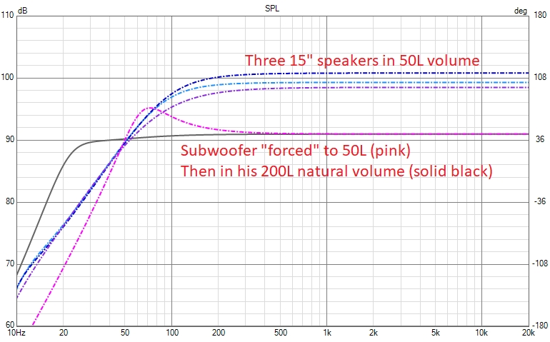
We can see the effect of sensitivity on the speaker’s output, but it doesn’t impact low-end response below 50hz for the same amount of power amplification if the box volume is the same (all drivers have the same diameter).
We prefer to say, in this case when volume and driver size are the same, that some drivers have a “flatter” response in low end than others, rather than talking about bass extension — because below 50 Hz, the bass extension is actually the same for all of them.
When we use the recommended enclosure volume of 200L for this subwoofer, we see that we gain significant SPL in the very low end.
Woofer & Subwoofer Characteristics
Sensitivity indicates how loud a woofer gets with a given amount of voltage. A higher sensitivity woofer will produce more SPL at lower amplifier levels. However, sensitivity doesn’t directly translate to how much low-end a woofer can handle.
Low-frequency distortion is primarily linked to cone movement (extrusion) — the more the emitting surface moves, the more distortion we get. Sensitivity or EQ only change the amount of energy needed to reach that movement. This gives a clear advantage to larger woofers or subwoofers in terms of distortion at a given SPL.
Even if we equalize a high-sensitivity woofer to match the low-end response of a lower-sensitivity one in the same box volume, there is likely no significant difference in distortion, assuming the drivers share the same size and load (enclosure volume). Below 50 Hz, the SPL will be roughly similar for the same input voltage.
In this context, it’s not a problem to increase the low-end slightly with EQ on high-sensitivity woofers to achieve a flatter response, since the distortion remains primarily tied to cone excursion.
Of course, using a vented enclosure instead of a sealed one allows for higher SPL by recycling the rear energy produced by the driver. This is a clear advantage, even though vented enclosures require more volume.
Vented vs Sealed
When choosing a subwoofer design, two main options come up: sealed (acoustic suspension) and vented (bass-reflex) enclosures. While both have their place, some persistent myths and misunderstandings deserve to be cleared up — especially now that modern DSP and room measurements make deeper integration possible.
Bass Extension: Vented Wins
A vented subwoofer enclosure will always provide better low-frequency extension compared to a sealed one, assuming the same driver and enclosure volume. Thanks to the tuned port, vented boxes reinforce bass around the tuning frequency, offering more output at lower frequencies.
“Tight Bass” comes from proper modal control — not from the type of enclosure.
A common belief is that sealed subs produce “tighter” or “faster” bass. In reality, this tightness comes from the room’s modal response, not the enclosure type, of course the vented enclosure goes lower so require more attention to room correction with DSP. Below ~200 Hz, your room dominates the response with resonances and standing waves. If these aren’t managed — through acoustic treatment or DSP correction — the bass will sound boomy or smeared, no matter how “fast” your sealed sub is supposed to be.
Today, with affordable measurement tools and DSP, it’s possible to correct room modes precisely. This means that a well-designed vented subwoofer, placed and calibrated correctly, can sound just as tight and controlled as it should be — while going deeper and with greater efficiency than a sealed one.
The Port: Design Matters More Than You Think
Not all ports are equal. Many designs use slot (rectangular) ports, which are compact but far from optimal. Slots tend to generate higher air friction due to greater surface area contact, leading to more turbulence, chuffing, distortion and power compression.
The best-performing ports use a circular cross-section, which minimizes wall contact and supports smoother airflow. Among circular ports, the geometry of the flares is critical. For example, the hourglass port design featured a flat velocity port , delivers a flatter velocity profile minimizing noise, distortion and compression even at high SPLs. It’s one of the best examples of how careful port shaping can outperform conventional designs.
Final Thoughts
In the age of DSP and accurate measurement, the sealed vs vented debate shouldn’t be about subjective impressions anymore. A well-engineered vented subwoofer, with a proper port and correct room integration, can offer deeper, cleaner, and equally “tight” bass.
The key lies in system design, not dogma:
- Know your room and measure it in modal field
- Measure and correct modal behavior as desrcibed in this article
- Use braces and stuffing optimized enclosures and ports
Good bass isn’t about sealed or vented. It’s about control, design, and integration.
Another Myth: Heavy Cones Are “Slow”
It is often believed that lighter woofer cones produce “faster” bass, while heavier cones sound slower. In reality, a loudspeaker has no inherent “speed” — it faithfully reproduces the input signal. If it were truly “faster,” it would alter the frequency or timing of the signal, which constitutes distortion.
A heavier cone primarily lowers the system’s resonant frequency, enabling deeper bass extension, but this comes at the expense of reduced sensitivity because more energy is required to move the increased mass. Conversely, lighter cones typically have higher sensitivity and lower moving mass, which allows them to generally reproduce higher frequencies with less mechanical stress and distortion, but they cannot achieve the same deep bass extension or control at high excursion levels as heavier cones.
Ultimately, perceived “tightness” of bass is much more influenced by proper room integration and modal control than by cone mass alone—similar to the vented versus sealed enclosure debate see upper.
Some advanced woofers cone, with an optimized balance of mass, damping, and rigidity, can be relatively heavy yet still achieve excellent high-frequency extension, better than some dedicated midrange ones, with low distortion. This is sometimes accomplished through sandwich cone constructions (like those from AudioTechnology) or/and by pairing the driver with highly advanced motors (such as PURIFI designs). Therefore, generalizations about cone weight and performance are very difficult to make.
Ultimately, precise measurements with flat EQ, and bass extension simulation remain the definitive criteria to evaluate performance.
Subwoofer Setup and Integration
Even if we have a FIR DSP, so linear phase filtering, we don’t use it here as it will be very costly in TAPS as the frequency is lower and useless about phase at this frequency. We will search to cut between 50 and 80 hz optimally.
Measure the delay in cm and convert it to ms if the subwoofer is far, be sure to not have a reversed phase as we said for the woofer, you can check it with the same techniques.
You can correct the woofer response at the listening area by doing several measures by moving the mic in the listening area, not at just one position.
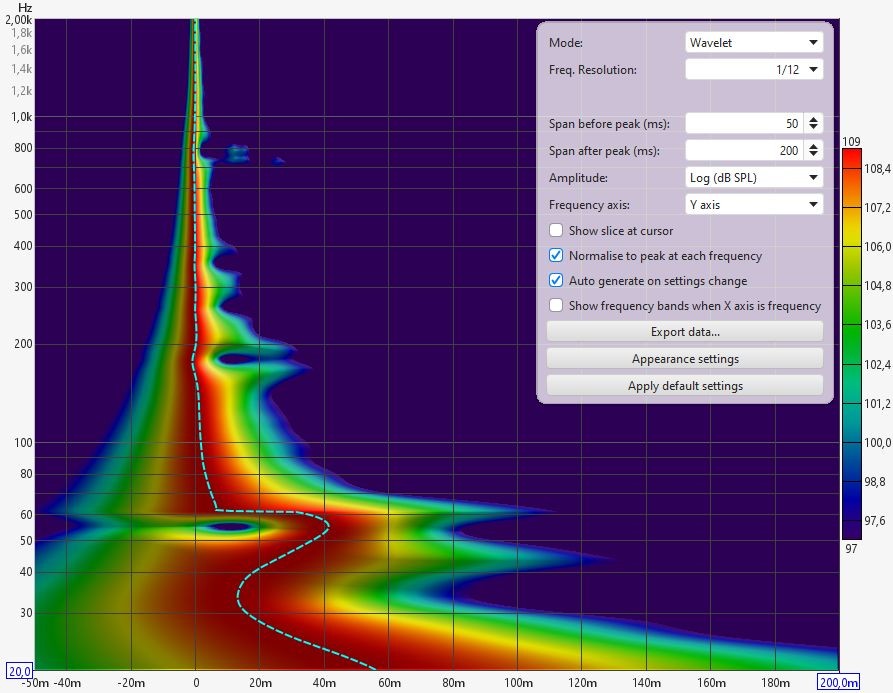
A regular EQ in minimal phase (“IIR”) placed on a modal effect with a quality coefficient (Q) equal to the modal effect will not only improve the frequency response but also the Time-domain behavior, reducing trailing bass and improving global bass experience.
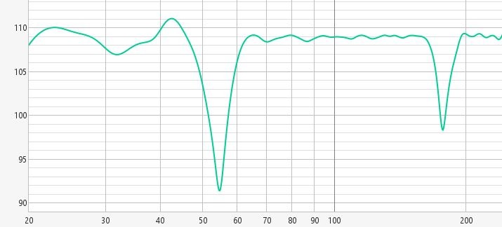
Clear cancellations should not be corrected, as the nulls move in frequency depending on microphone placement:
You can add an electric (in DSP) Butt 12 on your natural woofer natural fall to have a real (acoustic) Butt 24 in minimum phase filtering, linear phase filtering is not necessary at these frequencies.
Then add Butt 24 on the subwoofer as we have do in our speaker implementation article with woofer:
Note: Acoustic treatment will not solve or significantly reduce modal acoustic issues. The affected wavelengths are very long (several meters), and standard treatments are not deep enough to be effective in this range. Modal behavior is primarily determined by the room’s dimensions, geometry, and the placement of subwoofers or other low-frequency sources — the listener or microphone position, only affects how the modal field is perceived or measured at a given point or area.
Subwoofer and Masking Effect
Be careful when you correct or “boost” your subwoofer to not introduce a masking effect. A subwoofer should continue at the same existing SPL as the woofer.
If we want more bass — and more importantly, more kick — we can increase the SPL starting from around 200 Hz, gradually, to avoid inducing masking.
Increasing the subwoofer gain alone can lead to a vicious circle: the more gain we add to a subwoofer cut at 60 or 80 Hz, the more it will mask the kick in the upper range. That’s why, when we want more impact/kick, we don’t increase the subwoofer gain alone — we increase both the subwoofer and woofer SPL with EQ starting from 200 Hz accordingly.
If you boost the subwoofer in your system, you might notice a loss of impact or “kick.” This happens because excessive sub-bass will mask the upper bass and low midrange, where the kick drum energy typically resides.
To mitigate this masking effect:
-
Use EQ to carefully balance the spectrum. Start by gradually and smoothly increasing the bass response from around 200 Hz—where the kick is located— so that the woofer rises progressively in level and typically reach +5dB.
Stop increasing a little before your subwoofer crossover, around 60–80 Hz.
Then adjust the subwoofer so it takes over with a flat response, without continuing the upward trend of the woofer. The SPL transition between woofer and subwoofer should be seamless and flat, with no noticeable bump or gap.
This approach preserves the kick’s impact while avoiding masking effects. Keep in mind that it requires more excursion from the woofer in the upper bass region.We can see this approach in psyckoacoustics principles.
-
Avoid boosting the subwoofer level independently using its power amplifier gain. The way subwoofers are typically crossed over—often with steep filters and at low frequencies—can create a sharp SPL gradient if this gain boosting is applied.
This kind of abrupt gain change can effectively mask the upper bass and midbass, where the punch and energy of the “kick” reside. A well-integrated bass should extend smoothly from the main speaker’s response—not jump in level. -
Use dynamic processing (compression) to adapt the SPL of low frequencies at low listening levels. You can also use compression or shelving in DSP to reduce high frequencies at very high SPLs, maintaining a balanced perception.
Note: In home cinema setups that use an LFE channel (which adds bass content up to 120 Hz), this technique is not recommended. The LFE track already contributes significant low-end energy. In such cases, we recommend aiming for a flat bass response at the listening position.
We usually create two presets: one with a flat response, considered neutral, and another with a bass increase as described above.
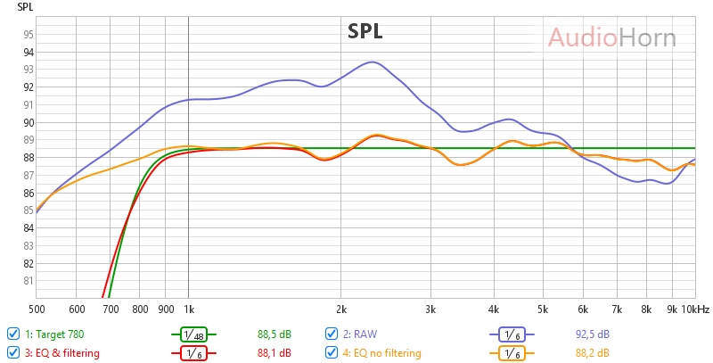
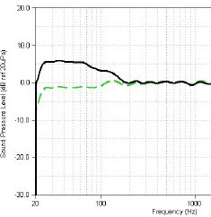
Here is a measurement showing an acceptable +5 dB transition from 150 to 100 Hz, but it could be made more progressive by extending this transition from 200 to 80 Hz.

Is Group Delay (GD) Audible in a Bass Reflex System?
It depends on the cycle length. Generally, it’s recommended that the GD should not exceed 1 or 1.5 cycles of the frequency, as this is related to its wavelength.
The formula for calculating the maximum acceptable GD is:
Δt max = n / f
Where:
- Δt max is the maximum acceptable group delay in seconds (multiply by 1000 to convert to milliseconds).
- n is the accepted cycle number (1 or 1.5)
- f is the frequency in Hertz
Example:
- For 40 Hz, Δt max = 1 / 40 = 25 ms
- For 20 Hz, Δt max = 1 / 20 = 50 ms
You can use VituixCAD Box Simulation to visualize the GD according to the box volume and port, and consider this information in your design and choices.
In practical cases, we don’t exceed the recommended GD limits if we follow standardized vent alignment so it will not be audible.
Subwoofer Positioning
Placing a subwoofer is a balancing act — we want to benefit from room gain without exciting problematic room modes. Unfortunately, the first rarely comes without the second.
A good rule of thumb is to position the subwoofer at about 20–25% of the width of the front wall, measured from each side wall. If you have multiple subwoofers, it’s best to group them in symmetrical pairs:
Source: Getting the Bass Right – Harman
Avoid placing subwoofers at the center of any room dimension (e.g., centered along a wall), as this can create a null in the center of the room.
Depending on your room size and desired maximum SPL, you’ll typically choose between one or two 12", 18", or 21" subwoofers:
- For maximum SPL, professional-grade subwoofers are the best choice.
- For a flatter frequency response, consider non-pro audio options such as high-end car audio subwoofers.
In most situations — except for very large rooms — a flat-responding subwoofer is what we aim for.
Below is a list of recommended subwoofers. For vented designs, look for a Qts between 0.33 and 0.36 and a low Fs (resonance frequency):
Vented:
-
Max SPL and top notch thermal compression : 18Sound 21NTLW5000
-
Pro that go low : BMS 18N862 (180L@25hz), 18Sound 18NLS4000 (100L@28hz)
-
Pro with good quality price : RCF 21X451, B&C 21SW115
-
Non pro, go low flat : Dayton RSS315HO-4 (12"), RSS390HO-4 (15") RSS460HO-4 (18") or Stereo Integrity HST-18 MkIII (only available in USA for this last one)
Sealed:
- Dayton Ultimax UM12, UM15, UM18
- All Stereo Integrity (USA only)
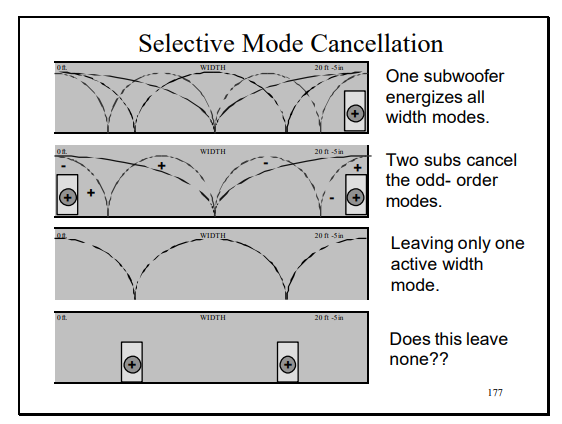
SBA and SBA
This particular positioning of sub is mentioned in our wavefront-propagation article
Horizontal Line Array of Subs
An alternative approach is to create a horizontal line of subwoofers along the floor, ideally integrated into the front wall. This setup spans the entire width between the side walls, with each subwoofer placed as close as possible to the next.
This configuration, while requiring many 18"/21" units, allows for plane wave radiation of the emitted bass when the wavelength of these frequencies is shorter than the length of the subwoofer array.
To ensure proper plane wave radiation, the array also needs to be digitally curved using arc delays — applying equal delay (calculated with an Array calculator) to the subwoofers at the ends of the array.
This requires using different DSP delays on the same channel, which in practice means using separate DSP output and amplifiers for each delayed group.
It’s a more advanced and expensive solution, often seen in systems like the Divatech subwoofer wall.
![]()