Dual woofer, MTM, MEH? 2, 2.5, 3 ways speaker?
MTM: A Trade-Off in Speaker Design
The MTM (Mid-Tweeter-Mid) speaker configuration offers advantages as high SPL capacties, but it also comes with challenges related to vertical lobing.
This article will describe specific mounting impact on the directivity, as mentionned in other article we listen at the so called critical distance where direct and reflected sound (from walls) are roughly balanced (50/50).
This impact on the directivity will also impacts the listening in-room experience, even when we are positioned in front of the speakers.
This article need a good comprehension about vertical lobing.
The MTM Lobing Issue:
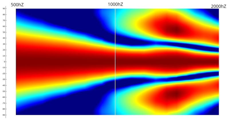
Placing two woofers in an MTM design increases the distance between their acoustic centers compared to a single woofer. This larger spacing can lead to vertical lobing, causing cancellation effects at certain frequencies, particularly when listening off-axis (from the side).
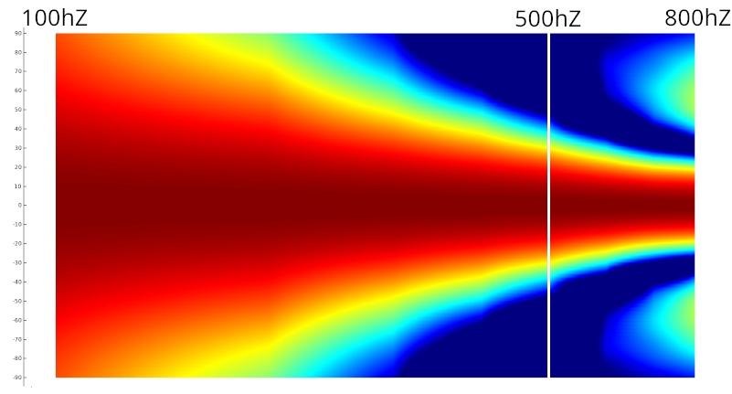
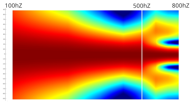
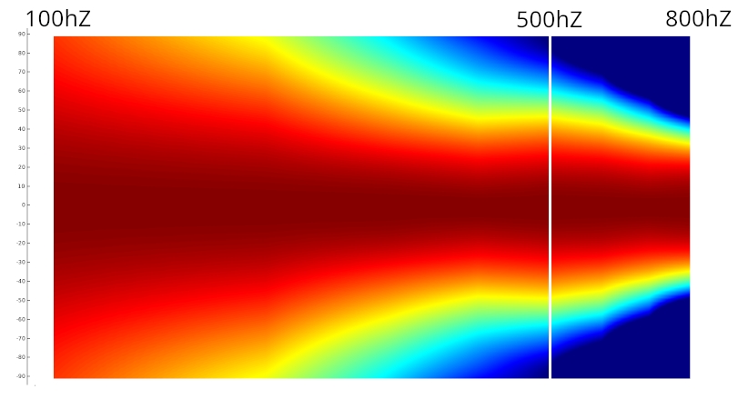
Here’s an image representing the difference in vertical off-axis response of a MTM design with Faital 12FE120 25cm spaced to let 12cm for the tweeter or the waveguide:
The MTM Vertical Directivity Issue
In an MTM (Midwoofer-Tweeter-Midwoofer) configuration, waveguides are often truncated to fit within enclosure constraints.
When the vertical aperture of the waveguide is reduced, for example from 60° to 40°, vertical directivity control is lost much earlier than intended—well before the horizontal control is lost, which typically aligns with the crossover frequency.
This results in three distinct phases: a controlled 40° vertical dispersion, a sudden transition to a much wider pattern (e.g., 95°-110°) when control is lost, and then an over-narrowing effect caused by vertical lobing.
Additionally, the loss of vertical aperture reduces acoustic loading, which further impacts the horn’s efficiency.
The MTM Diffraction Issue
Another critical issue with the MTM layout is vertical diffraction. The wavefront from the waveguide interacts with the two symmetrically positioned midwoofers, effectively encountering two reflective sources above and below. This symmetrical diffraction not only reinforces interference artifacts but also leads to an increase in diffraction energy, multiplying its impact.
From the perspective of the waveguide, the sound front interacts with both woofers as additional sources of diffraction, significantly affecting polar response. The smaller the waveguide and the closer the midwoofers, the more pronounced this effect becomes, regardless of the crossover frequency.
Additionally, even the horizontal polar responses are negatively impacted by the vertical symmetrical double diffraction effect caused by the symmetrical placement of the woofers. This amplifies inconsistencies in dispersion, making the overall response less predictable.
Combined with the presence of vertical lobing, these factors contribute to a disrupted and inconsistent radiation pattern.
Addressing the Issue in MTM:
While MTM presents a lobing challenge, there are ways to mitigate it:
-
Lower Crossover Frequency: In MTM designs, using a lower crossover frequency for the woofers can help reduce lobing. However, this asking more power for the compression driver and can be hard to achieve or even lead to a burned compression driver.
-
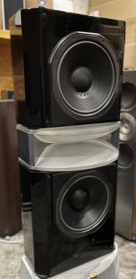
2.5-Way Design: If you’re set on an MTM layout, a 2.5-way crossover design can be a solution. In this design:
-
The bottom woofer is crossed over with the tweeter at a higher frequency.
-
The other woofer is crossed over at a lower frequency and compensated baffle step loss.
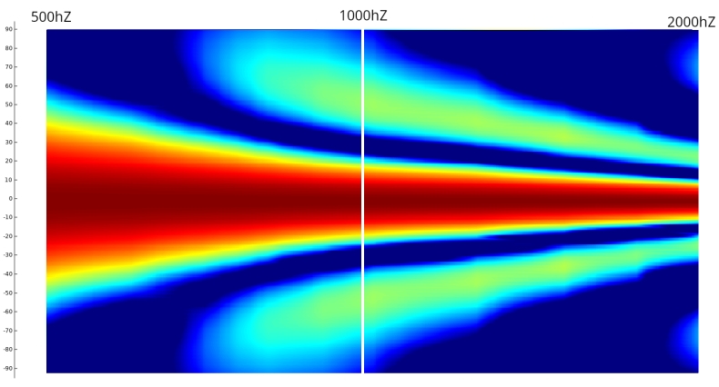
This approach helps maintain a good on-axis response while minimizing lobing effects and keeping high SPL capacities.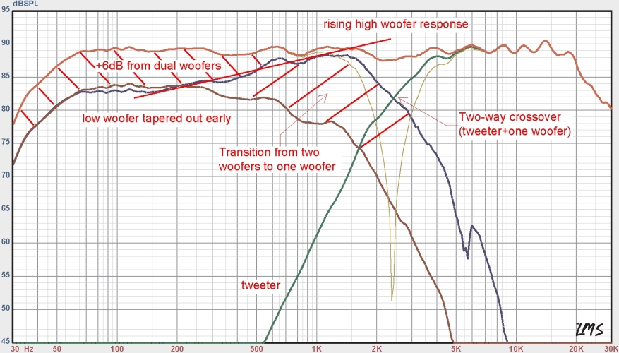
This approach was also helpful to maintained a good sensitivity for passive speaker, for active one the remaining advantage is to have a little more SPL capacities bellow 200/300hz, in very high SPL demanding apoplication it can be usefull (night club)
-
-
Try to use fluid design
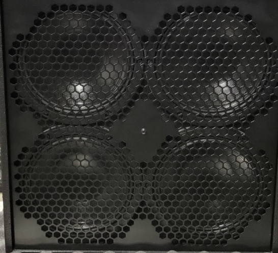
Another solution is to narrow each “M” of the MTM to reduce the vertical lob impact.
It can be done by replacing each “M” by 4 drivers forming a compact square, the number of drivers in this solution is puch to 8 by speaker, 4 at the top of the HF section and 4 at the bottom.
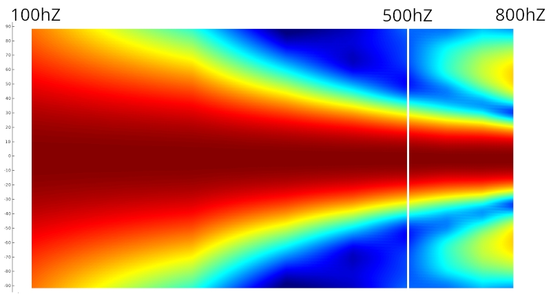
The vertical polar will be :
We will see in next chapiter that this kind of quadro arrangement can also be used outside of MTM strategy.
Alternatives to MTM:
It’s important to consider the context when choosing a speaker configuration.
-
Subwoofer Integration: If you’re using a subwoofer, the benefits of dual woofers or MTM become less significant, even in 2.5 voices.
-
Long-Range Listening with high SPL usage: For long-distance listening with high sound pressure levels (SPL), a 3-way speaker system might be more suitable, with or without subwoofer.
TMM
Older conceptions utilized a wide horn, approaching 60cm in width, with two 15" woofer horzontally placed such as the TAD TSM 1:
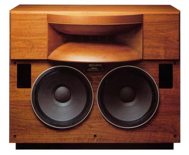
In this configuration, achieving directivity matching could only be accomplished with dual 15" woofers placed side-by-side. Theoretically, this arrangement, with the 15" drivers positioned as closely as possible, would leverage horizontal lobes to create a more restricted directivity pattern.
Finite Element Analysis (FEA) simulations were employed to model real woofers within this arrangement.
While these simulations yielded results, the narrowing of the directivity pattern was excessive, as the 15" drivers centers remained relatively far apart:
If an internal radius is introduced to bring the woofers closer together by “pinching” the box from the inside:
Alternatively, an external radius can be employed to bring the woofers closer by “pinching” the box from the outside:
While this approach introduces some “blurring” of energy due to the driver orientation, the resulting directivity pattern is still excessively narrow. Since the “pinching” is external, the negative throat effect observed with the internal pinch is no longer present.
This system can function, but it necessitates a large horn with a 1m mouth and an 80° flare angle cut off at 400Hz, or a 70° flare angle cut off at 450Hz.
Modern coaxial compression drivers can reach 400/450Hz, but not at high output levels, as the voice coil would overheat. This type of arrangement appears more promising with 12" or 10" woofers, allowing for closer driver spacing.
Further simulations demonstrate that with a 1.4" driver crossed over around 600Hz to a 60/65cm 90/80° horn, the dual 10" configuration appears to be the most suitable:
We have to keep in mind that a change is the center to center spacing beetween both woofers have a huge impact on the polar response, it should be simulate in FEA before.
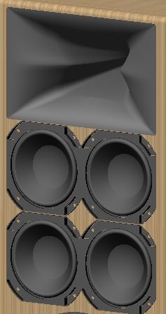
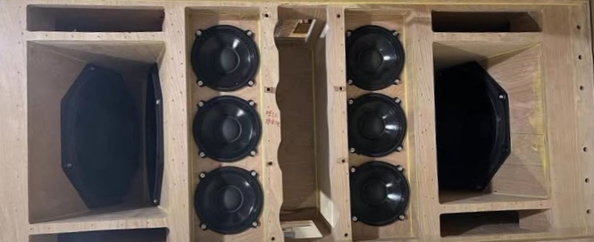
The solution can be to push to restrict vertical directivity in this way, using a “quadro” configuration:
This solution is useful for creating a radiation surface between one 15" woofer and two horizontal woofers.
We have simulated this arrangement with four Faital 5FE120, which fit well with the X-Shape X25 or X28 in a TMM/MM arrangement. MMTMM must not be used, similarly, an 7/7.5-inch quadro in a TMM/MM configuration below an X-Shape X40 at a crossover frequency of 700-750 Hz is interesting.
It’s important to note:
-
The improvement due to the lobes will be mainly present if the driver size and position are carefully chosen to match the horn directivity
-
The effect mainly applies around the crossover in comparaison to a regular well implemented TM arrangement, see next chapter why.
-
Lobes created by multiple drivers (MM or MM/MM) suppress the impact of mid range narrowing through their own cancellation.
-
When the enclosure width is significantly larger, using two 15" woofers will result in an excessively narrow radiation pattern, even with slight adjustments, it’s an old design that show some limits.
-
MTM can be used in “quadro” woofer arrangement (MMTMM) but the generated vertical directivity will make a good vertical directivty match impossible, it’s not recommended but to fix it we can use a doble quadro configuration
Lobs in Line array
LOBs can often be used in line array units to control radiation on both axes to respect the WST criteria:
This approach is specifically designed for large line arrays. Tiny line arrays cannot effectively cross low with subwoofer lines. The height of the line array directly influences the lowest frequency at which it produces plane wave radiation, with taller arrays achieving lower frequencies control.
However, line arrays require significant space in environments. To effectively control radiation at 80Hz, a line array might need to be 5 meters long and positioned far from any surfaces or obstacles, even ground. This is crucial because the cylindrical wavefront produced by the line array must remain unobstructed to maintain its integrity. Any obstruction will disrupt the wavefront and degrade the system’s performance.
Line arrays are composed sources consisting of multiple units that combine to create a single perceived system. These individual units act as single primary point sources, each radiating sound waves. The combined effect of these waves creates the final characteristic of the composed sound, particularly at a certain distance. It will take distance (aka time) for the cylindrical or even the initial plane wavefront to form.
Midrange Narrowing and directivity impact
We can easily make a simpler box, just large enough for the mid-woofer, and combine the natural directivity of the mid-woofer with its midrange narrowing to achieve a perfect directivity match with the horn at crossover region.
Consult our article on midrange narrowing effect to know more.
A point about Polar
We need to pay attention to scale in polar plot. A “half-space” option in VituixCAD displays the polar response over 180° instead of 360°. If we stay in the 360° mode, the scale is affected, and the polar response may appear more consistent than it actually is.
The same issue exists with the color scale, where using solid colors for a 2 or 3 dB range instead of a gradient can hide certain problems.
Lastly, an even simpler issue is with polar maps that start at 0 dB or use the same color for ranges like +6 dB to -2 or -3 dB (and sometimes even down to -6 dB). This completely obscures the true response of the horn.
The yellow color should also be on the -6dB and not -10dB to not hide everything in the red color.
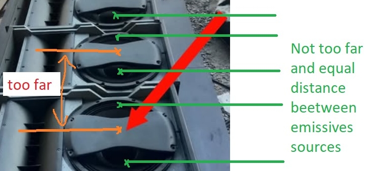
MEH and Synergy horn
Synergy Horns are a fine solution to reduce size and make portable speakers for PA usage. However, their directivity can be quite uneven. This is not a significant issue outdoors without walls, but indoors, when we listen to a combination of direct sound and sound reflected from walls, it can result in an uneven and less than ideal listening experience.
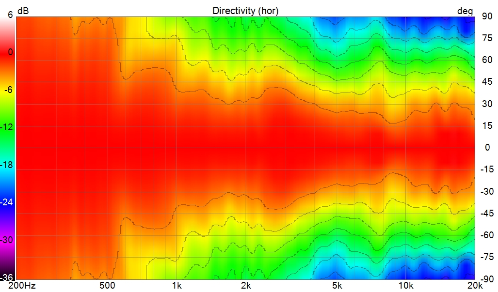
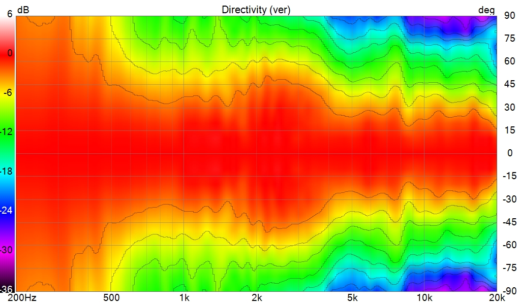
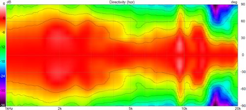
Here are some rare and hard-to-find horizontal polar plots of three different MEHs. One of the plots was originally in 4π and has been adjusted to 2π (Half Space) to better illustrate what happens:
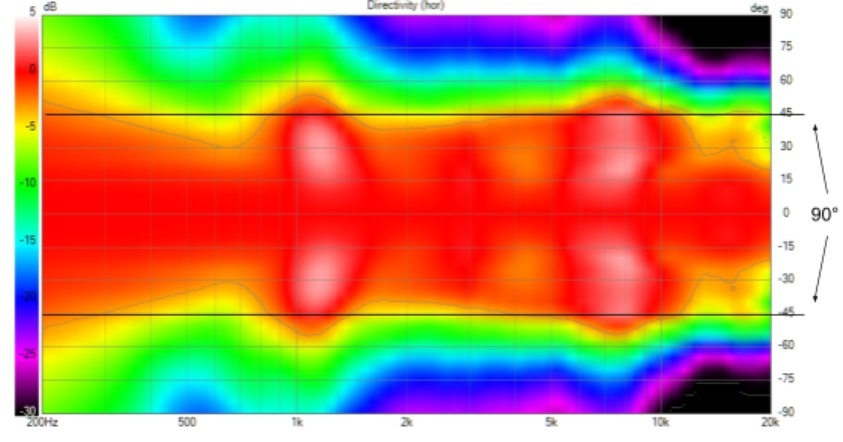
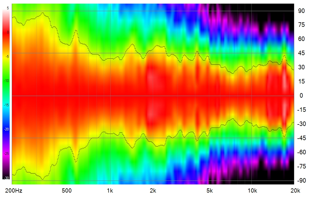
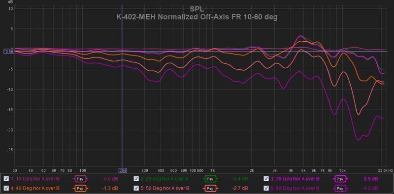
MEHs (Multi Entrance Horns) use multiple speakers positioned at different entrances along the horn to achieve “point source” and create a directivity thanks to lobes but unlike a single source, these multiple entrances generate not only interference lobes in the frequency response but also internal reflections that can alter temporal coherence. In particular, the speakers placed on the sides inject acoustic energy that can partially reflect back into the horn, creating a return wave. This phenomenon modifies the acoustic impedance perceived by the speakers, which can induce additional reactance.
In addition to this effect, several other issues may arise:
- Comb filtering and interference: The multiple entrances create destructive and constructive interferences depending on frequency and listening angle, which can affect the linearity of the frequency and phase response. That we can see on polar upper.
- Variable acoustic load: The reactance caused by internal reflections can modify the coupling between the transducers and the horn unevenly across frequencies, impacting the sound radiation efficiency.
- Excitation of resonant modes: Certain horn geometries can amplify specific frequencies due to internal reflections, creating parasitic resonances.
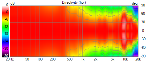
Coaxial
Here, we will examine the measurement of the KEF R3 in half-space, widely considered one of the best coaxial speakers on the market, featuring a 100% fluid profile.
The coaxial arrangement avoids lobing between sections at the crossover. However, the mid-woofer section now serves as a waveguide for the tweeter, introducing challenges in maintaining consistent directivity — especially due to the tweeter–woofer junction but also to the surround diffraction.
For DIY purpose:
Sica 6.5C1.5CP
Satori MT19CP
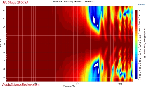
In pro section the B&C 10FCX64:
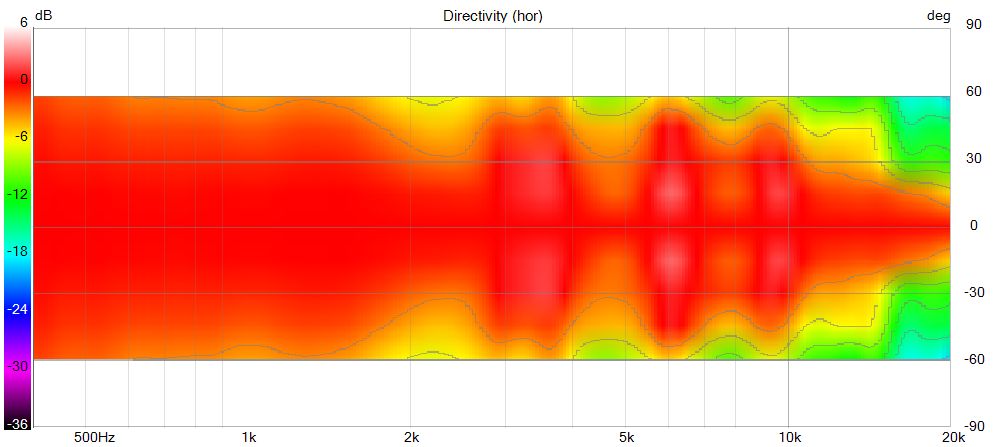
For in-wall section the JBL STAGE series:
Point source
The concept of a “point source” is often advanced as an advantage of MTM or MEH (Multiple-Entry Horn) speaker arrangements.
Perception of a point source is primarily due to the coherent summation of sound waves between the drivers. These aspects are highly dependent on the center-to-center spacing between each driver proportionally to the wavelength of the crossover frequency, but not only.
The listening distance plays a significant role. A system listened to at 1 meter behaves differently than listened at 6 or 30 meters: At sufficient distances, even a large line array is considered as a point source.
Any well-designed and properly crossed lower enough loudspeaker system, especially those employing horns, will exhibit point-source behavior at a certain distance relatively fast, even the bigger ones, it’s more a question of implementation.
The “problem” of not being a “true point source” is primarily relevant in niche scenarios like tiny speakers used on desktops at very close distances (50-70 cm). In such cases, a small coaxial driver can effectively address this concern. However, from an acoustic perspective, this is not a rel issue in real-world listening situations, even in a regular room.
Vertical diffraction and impact on vertical directivity:
In this article about diffraction, we can see that vertical diffraction significantly impacts vertical directivity due to the surrounding environment and the shape that the wavefront encounters, it should be taken in account too.
![]()