Free-Standing vs In-Wall Mounting: Directivity Considerations
Introduction
The way a loudspeaker is mounted — free-standing or flush-mounted in a wall — has a major influence on its directivity behavior, particularly around the crossover region.
Proper directivity matching ensures that the woofer is crossed over when it becomes sufficiently directive, while the horn or waveguide is crossed over when it starts to lose its controlled directivity, creating a smooth and coherent transition between the two drivers.
An oversized cabinet or a rigid in-wall installation can widen radiation at the crossover frequency, making proper directivity matching with a horn extremely difficult, and can degrade directivity control below this region until wavelengths become sufficiently large.
This article focuses on understanding these mechanisms and identifying practical solutions.
1. Free-Standing Case
Smooth horn and waveguide design
For horns and waveguides, the profile must be smooth and continuous along the axis of wave propagation.
Rounded edges and the absence of abrupt depth changes ensure a consistent progression of the wavefront and stable directivity, midrange narrowing must be avoided.
Woofer directivity and baffle size
In the case of a woofer, its directivity can approximate that of a similarly sized horn at crossover if the enclosure is just large enough to house the driver.
This is the key design principle: the cabinet should not be oversized. By limiting the baffle width, the resulting midrange narrowing occurs at the intended frequency,
allowing it to cooperate with the woofer’s natural directivity transition.
In this specific case, crossed with a 90° horn, the cabinet does not need a roundover. Leaving the corners sharp or minimal (without rounding or 4mm) will be advantageous, as it allows us to exploit edge diffraction to complement the horn’s natural directivity.
A properly sized baffle ensures that:
- The midrange narrowing occurs where the woofer starts to become directive,
- The woofer’s polar response aligns smoothly with the horn’s controlled directivity at crossover,
- Directivity match is optimized without introducing wavefront distortions or frequency shifts.
If the baffle is made too large, the midrange narrowing shifts to a lower frequency, the woofer does not become directive enough at the intended crossover, and optimal directivity matching with the horn becomes impossible.
Wavefront distortions with oversized baffles
At mid and high frequencies, an oversized baffle distorts the wavefront leaving the driver.
Part of the sound propagates at very shallow angles along the baffle surface (quasi-lateral wave), while abrupt edges excite evanescent near-field components.
Their interaction with the main propagating wave alters the overall wavefront, resulting in uneven radiation and degraded directivity
until the wavefront becomes dominated by wavelengths larger than the baffle, at which point these distortions gradually vanish.
Matching woofer and horn directivity
The directivity of a mid-woofer evolves with frequency:
- At low frequencies, radiation is wide and close to omnidirectional.
- As frequency increases, directivity narrows progressively as the effective radiating diameter becomes limiting.
By ensuring the baffle is just large enough for the woofer, the midrange narrowing occurs at the intended frequency, cooperating with the woofer’s natural directivity transition.
This allows the woofer’s polar response to blend smoothly with the horn’s directivity at the crossover, achieving a predictable and coherent directivity match.
2. In-Wall Case
Directivity behavior in wall installations
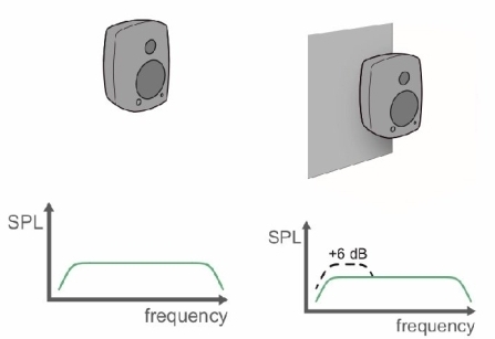
When a loudspeaker is flush-mounted in a rigid wall, radiation is confined to a half-space (180° hemisphere, or less in corners).
This increases output at very low frequencies, but around the crossover region it often creates a severe directivity mismatch.
In this configuration, the woofer’s radiation becomes wider than in free-standing conditions and typically wider than the horn’s controlled directivity (often around 90°), resulting in an uneven directivity index transition.
Note: An in-wall installation does not remove the need to aim the speaker toward the listening position.
The front wall must be shaped accordingly; a flat wall is not sufficient.
Wavefront behavior with a hard wall
When a waveguide is flush-mounted in a rigid wall, the wavefront does not detach cleanly into space.
Three contributions coexist:
- the main propagating wave,
- a quasi-lateral wave traveling along the wall surface,
- evanescent near-field components excited by opening edges (including those of the woofer itself).
Their interference alters the phase and curvature of the wavefront, producing irregular radiation and directivity anomalies.
The observed directivity anomalies in rigid in-wall installations are caused by the combined interaction of propagating and non-propagating wave components near the mounting surface.
Evanescent near-field components are generated at sharp impedance discontinuities such as waveguide terminations, driver apertures, and cabinet or woofer edges. Although these components do not propagate into the far field on their own, they modify the local pressure and particle velocity distributions near the wall. When coupled to a rigid boundary, they can partially convert into propagating energy at larger distances, altering the effective phase and curvature of the radiated wavefront.
In addition, the woofer’s initial wavefront contributes to these anomalies. Its near-field radiation is not a well-defined planar wave; local pressure and velocity variations, arising from diaphragm motion, geometry, and driver-edge discontinuities, coexist with a chaotic, quasi-reactive region immediately in front of the driver, a non-radiative zone where the acoustic field is not yet fully propagated, with pressure and particle velocity out of phase, and where energy is partially stored rather than radiated efficiently.
Note: this aspect also makes designing a woofer waveguide challenging, because the waveguide sees the near-field wavefront before it reaches the Fresnel region, where the front is highly non-uniform and varies with frequency.
In an in-wall installation, these irregularities interact with the evanescent components and quasi-lateral waves, amplifying directivity anomalies even when the cabinet front is flush.
In parallel, quasi-lateral waves are excited along the rigid wall surface due to the strong acoustic impedance contrast between air and the boundary. These waves are neither purely standing waves nor free-field radiation. They are guided surface-related modes that transport energy laterally before re-radiating into the listening space. Their delayed and frequency-dependent re-radiation interferes with the main wavefront, producing lobing, angular irregularities, and non-monotonic directivity index behavior.
These effects become most pronounced when the natural directivity of the radiator becomes narrower than the hemispherical radiation imposed by the wall. In this regime, the wavefront cannot detach cleanly from the surface, and the wall enforces an artificially wide radiation pattern that contradicts the source’s inherent directivity. The result is not simple midrange beaming or diameter-related narrowing, but an unstable transition dominated by boundary-induced wave phenomena.
Moreover, the rigid wall forces the woofer to radiate over a wider angle near the crossover region. As a result, its directivity can exceed that of the horn at the crossover frequency, making the transition region prone to off-axis irregularities.
As frequency decreases and wavelengths become much larger than the source, these effects progressively vanish and radiation approaches ideal half-space behavior at very low frequencies.
The constricted radiation gain provided by the wall, from 4π to 2π for example, occurs only when the natural radiation of the driver is wider than the available aperture of the wall, typically at low frequencies.
When the natural directivity at a given frequency becomes narrower than the hemispherical radiation (~180°) imposed by the mounting surface, the wavefront must detach and radiate freely into half-space.
If the wavefront cannot detach properly at that point, the wall forces an artificially wide radiation pattern, reintroducing the very mechanisms described above: quasi-lateral waves, evanescent near-field components, and severe directivity irregularities.
Solution: Acoustic absorber wall
For stable directivity, the wavefront must detach and radiate freely into half-space at the appropriate frequency.
This is achieved by using absorptive or porous materials around the horn and a relatively thin woofer enclosure, providing an acoustic impedance closer to that of air.
Such treatment suppresses lateral wave propagation and evanescent components, leaving only the main propagating wave to define directivity.
The front wall should be flush with the enclosure and acoustically absorptive, which not only stabilizes directivity, but also improves the room’s acoustic behavior.
It will also help, as in a free-standing ideal implementation (see above), to preserve the directivity match between woofer and horn, as the wavefront can beam naturally and combine with the woofer’s inherent directivity to reach the horn’s radiation at the intended frequency.
If this cannot be achieved, a free-standing configuration respecting proper baffle dimensions will generally yield better results, as the room or wall cannot reliably act as a horn except in the very low frequency range.
Conclusion
Mounting conditions have a critical impact on loudspeaker directivity, particularly around crossover frequencies.
Free-standing designs with well-proportioned baffles allow controlled use of midrange narrowing for directivity matching, while in-wall installations require careful absorptive treatment to avoid severe radiation anomalies.